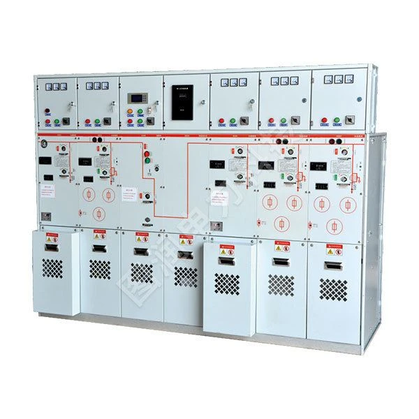
XGNSF6-12 SF6 Gas Filling Cabinet
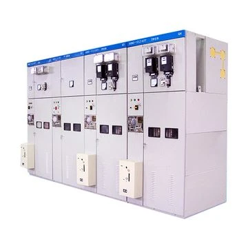
The XGNSF6-12 series SF6 fully insulated metal-enclosed compact metal switchgear (hereinafter referred to as gas-insulated switchgear) adopts a modular design, combining fixed and flexible expansion to meet the requirements of end users or network nodes. It also meets the needs of various power distribution substations, box-type substations, and cable branch boxes, and features compact structure, safety and reliability, long service life, and maintenance-free operation.
Normal usage conditions
|
Altitude |
≤2000 meters |
|
Ambient temperature |
-40 degrees Celsius to +40 degrees Celsius |
|
Seismic resistance |
8 degrees, horizontal acceleration ≤ 0.4g, vertical acceleration ≤ 0.2g |
Technical characteristics
- SF6 gas pressure: 1.4 bar (absolute pressure) at 20 degrees Celsius.
- Annual leakage rate: ≤0.25‰
- SF6 gas chamber protection rating: IP67
- Immersion test: Apply 0.3 bar pressure underwater for 24 hours.
- Fuse sleeve: IP67
- Arc ignition test: With arc extinguisher 20kA/1s; Without arc extinguisher 16kA/1s
- Stainless steel shell thickness for the air chamber: 3mm
Structural Design
The gas-insulated switchgear consists of five compartments: switch-busbar compartment, operating mechanism compartment, fuse compartment, cable compartment, and pressure relief compartment.
■ Switch-busbar compartment
After the three-phase load switch is debugged as a whole component, it is installed in the gas box.
The switch has a rotary three-position structure, combining isolation and grounding functions. The stationary contact is equipped with a curved metal grille to enhance deionization during arc extinguishing.
To optimize the electric field distribution within the gas tank, the main busbar is designed as a rectangular copper busbar with R5 rounded corners. The ring network busbar and the transformer circuit busbar are Φ20 and Φ20 respectively.
The Φ10 copper rod is equipped with a metal shield at the sharp points that may cause local electric fields, such as busbar connections and fixing points, in order to uniformize the electric field and improve the insulation strength.
■ Operating mechanism room
The operating mechanism compartment is located in the upper part of the TRC-12 series gas-insulated switchgear. The mechanism rollers are tightly fitted to the switch operating panel and fixed with bolts. The mechanism is available in single-disc spring (incoming line mechanism) and double-disc spring (outgoing line mechanism), respectively matched with ring network and transformer circuit switches. The disc spring mechanism features high assembly precision, low operating force, long service life, and high stability.
The coil spring mechanism is available in both manual and electric operation modes. The motor can be either DC220V, AC220V, DC48V, or DC110V.
The institution itself has two lines of defense against misoperation:
First, there are the interlocking plates with mandatory protection installed within the mechanism, which will remain in place unless the operator forcibly damages them:
Secondly, the external protection provided by the position indicator baffle prevents the operator from inserting the handle into the locked operating shaft hole.
■ Fusible gas chamber
The fuse compartment (fuse sealing chamber) is located in the middle of the gas-insulated switchgear and is housed in a gas box filled with SF6 gas. The fuse sealing chamber consists of an epoxy resin insulating cylinder cast using APG technology, and upper and lower conductors (end caps). Both the upper and lower conductors are shielded to optimize the electric field and improve the insulation level of the fuse sealing chamber.
The fuse's striker mechanism is linked to the main circuit via a pull wire. When the fuse blows, the pull wire trips, causing the switch to open. A fuse activation indicator is located on the front door for easy observation and maintenance. The fuse can be easily replaced by unscrewing the end cover using the operating handle.
■ Cable room
The gas-insulated switchgear has ample space for cable installation, with cable connection heights up to 600 mm. Each unit's cable compartment is separated by aluminum-zinc coated steel sheets for easy maintenance and repair. Most of the remaining space can be used to install current transformers and other control and protection devices.
The cables are connected using prefabricated cable connectors, which can be shielded or unshielded, or equipped with surge arresters. A grounding busbar is installed at the bottom of the cable compartment.
■ Pressure relief chamber
The pressure relief chamber is open, located at the lower rear of the gas holder, and isolated from other compartments. The lower part of the gas tank is equipped with pressure relief valves, the number of which is the same as the number of circuits. In the event of a major accident and malfunction of the protection devices, the high-pressure gas generated inside the gas tank releases pressure through the pressure relief valves, thereby ensuring the safety of operators and adjacent equipment.
Products Description
■ Sealing process
Except for the welded areas, all other seals on the gas box are sealed with O-rings (the switch shaft is sealed with a double-layer oil seal or a magnetohydrodynamic seal). The O-rings are custom-made, and their materials, diameters, and cross-sections have been carefully designed and verified to ensure that their compression and aging resistance are within the appropriate range, guaranteeing that the gas box will not leak during its service life.
Annual leakage rate of gas-insulated switchgear ≤ 0.25‰
■ Extend
The gas-insulated switchgear features a modular design, with each switchgear connected via insulated connectors. It offers strong expandability and flexible assembly, and eliminates the need for on-site SF6 gas handling. In the event of an accident, each switchgear can be detached and quickly replaced, ensuring rapid restoration of operation and improving product utilization.
■ Gas pressure
At 20°C, the rated pressure of SF6 gas is 0.04 MPa (gauge pressure), and the pointer being in the green area indicates normal pressure.
Regarding the requirements for SF6 switchgear operation and withstand voltage test under zero gauge pressure, referring to the standard DL/T615 1 997 "Guidelines for the Selection of Parameters of AC High Voltage Circuit Breakers", it is considered that the gas box under zero gauge pressure contains a mixture of air and SF6 (the ratio is difficult to determine), and its insulation strength is unstable. Operation is also unreliable. At this time, the pressure should be increased to the specified rated pressure (or the pressure gauge pointer is in the green zone).
■ Transportation
The gas cabinet is equipped with lifting rings for hoisting, and can also be moved by forklifts using a forklift lift.
Gas-filled cabinet weight: Standard 1 unit weighs 130kg, 2 units weigh 250~260kg, 3 units weigh 300~310kg, 4 units weigh...
The weight of a single unit is 390~430kg, and the weight of 5 units is 480~660kg.
Storage
Before installation and use, the gas-filled cabinet must be stored in a dry and well-ventilated place and covered with a plastic bag.
The base must be level during installation. Determine the foundation size according to the number of modules or units, and fasten the cabinet to the pre-embedded channel steel.
Each mold of the gas chamber has the following configuration
For the configuration and characteristics of cabinet D, please refer to the "Standard Configuration and Characteristics of Cable Connection Module without Grounding Switch".
For C-cabinet configuration, please refer to the standard configuration and features in the "Loading Module".
For F cabinet configuration, please refer to the standard configuration and characteristics in "Load Switch Fuse Combination Electrical Appliance Module".
For V-cabinet configuration, please refer to the "Standard Configuration and Characteristics" section in the "Vacuum Switch Module".
The standard package also offers the following configurations
- The capacitive voltage indicator of the incoming bushing is installed in each gas chamber, along with a pressure gauge to monitor the SF6 density. Lifting lugs and operating handles are also included.
- The TRC-12/24KV offers the following 10 module types: DF, CF, CCF, CCC, CCCC, CCCCC, CCCCCC, VVVVVV, VC, and VCCCCC. Up to 6 units can be manufactured; if more than 6 units are needed, expansion is required.
Available modules
C. Load switch module (width = 325mm)
De Cable connection module with grounding switch (width = 325mm)
D. Cable connection module without grounding switch (width = 325mm)
F Load switch fuse combination electrical module (width=325mm)
C Vacuum switch module (width = 325mm)
SL busbar sectionalizing switch module (load switch) (width = 325mm)
Sv busbar sectionalizing switch module (vacuum switch)
The SV is always located together with the busbar lifting module (width = 650mm).
Be bus grounding module (width = 325mm)
M meter module (width = 695mm)
CB Vacuum Circuit Breaker Module (Width = 600mm)
Overview
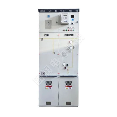
The TRC-12 fully enclosed, fully insulated gas-filled ring main unit (RMU) is an SF6 gas-insulated metal-enclosed switchgear. The equipment can be composed of modules including load switch units, load switch-fuse combination units, vacuum circuit breaker units, and busbar incoming units. Adopting a series of advanced technologies and materials, it features excellent electrical and mechanical performance, is minimally affected by environmental and climatic conditions, has a compact size, and is easy to install, convenient to operate, maintenance-free, and features a flexible combination method. The clear and intuitive design ensures simple and direct operation. With a large feeder connection capacity, it is suitable for various wiring systems.
Module Definitions
|
Module Code |
Meaning |
|
C |
Load Switch Unit (Standard single bushing load switch unit) |
|
F |
Load Switch-Fuse Combination Unit |
|
V |
Circuit Breaker Unit |
|
D |
Cable Incoming Unit (Without switch) |
|
+ |
Busbar Side Bushing |
|
- |
Busbar Top Bushing |
|
SL |
Bus Tie Unit |
|
M |
Metering Unit |
|
PT |
PT Unit (Voltage Transformer Unit) |
|
1K2(4) |
Load Switch Unit with Double Outgoing Bushings |
Product Features
■ Operational Safety: Integrated three-position load switch. We provide users with exceptional safety protection through the following safety measures:
Replacing the disconnector switch with a load switch makes it safer and more reliable. The fully sealed design on one side prevents accidental contact. The mechanical interlocking and live line indicators meet the "Five-Prevention" requirements, providing live line indication for incoming and outgoing circuits.
■ Reliable Operation: Fully sealed design ensures reliable operation. All 10kV switches and busbars are sealed in a 3mm stainless steel gas tank equipped with silicone rubber cable plugs. This achieves full insulation and full sealing for the cables, preventing external environmental factors such as dust, humidity, and small animals from affecting the internal components. The spring energy storage operating mechanism allows manual or electric operation. A mimic diagram on the front panel indicates the switch positions, and the cabinet body is made of galvanized steel plates with an electrostatic spray coating, enhancing its corrosion resistance. The pressure gauge monitors the SF6 gas safety pressure range inside the gas tank.
■ Economy: Maintenance-free. Highly reliable.
■ Flexible Schemes:
Multiple incoming line methods: left, right, top, or front.
Various combinations: arbitrary combinations between various units.
Insulated busbars are used, allowing connection either before or after cabinet assembly, or left/right connection.
■ Wide Application: Large feeder capacity, small footprint, suitable for various applications.
Performance Indicators
|
SF6 Gas Pressure |
Absolute pressure 1.4bar at 20℃ |
Normal Operating Environmental Conditions |
|
|
Annual Gas Leakage Rate |
0.2% / year |
Upper Limit Temperature |
40℃ |
|
Protection Level |
IP67 |
Lower Limit Temperature |
-40℃ |
|
Gas Chamber Stainless Steel Thickness |
3.0mm |
Upper Limit Avg. Relative Humidity |
≤ 95% |
|
Busbars |
Altitude |
≤ 2000m |
|
|
Busbars inside Switchgear |
400mm²Cu |
||
|
Grounding Busbar of Switchgear |
150mm²Cu |
Compliant Standards |
|
|
Colors |
GB/T11022, GB3906, GB1985 |
||
|
Switchgear Front Panel |
RAL7012 |
GB16926, GB38041, GB1984 |
|
|
Side Panels and Cable Compartment Front Cover |
RAL7035 |
GB3309, IEC60056, IEC60129, IEC60265, IEC60298, IEC60420, IEC60694 |
Auxiliary Equipment Parameters
|
Item |
Unit |
C Module Load Switch |
F Module Combination App. |
V Module Vacuum CB |
V Module Isolating/Earthing Switch |
CB Module Vacuum CB |
CB Module Isolating/Earthing Switch |
|
Rated Voltage |
kV |
12 |
12 |
12 |
12 |
12 |
12 |
|
Rated Frequency |
Hz |
50 |
50 |
50 |
50 |
50 |
50 |
|
Power Frequency Withstand Voltage (Between Phases / Opening Gap) |
kV |
42/48 |
42/48 |
42/48 |
42/48 |
42/48 |
42/48 |
|
Lightning Impulse Withstand Voltage |
kV |
75/85 |
75/85 |
75/85 |
75/85 |
75/85 |
75/85 |
|
Rated Current |
A |
630 |
Note |
630 |
- |
1250/630 |
- |
|
Rated Closed Loop Breaking Current |
A |
630 |
- |
- |
- |
- |
- |
|
Rated Cable Charging Breaking Current |
A |
135/135 |
- |
- |
- |
- |
- |
|
Rated Short-Circuit Making Current (Peak) |
kA |
50 |
80 |
- |
- |
- |
- |
|
Rated Peak Withstand Current |
kA |
50 |
- |
- |
- |
- |
- |
|
Rated Short-Time Withstand Current |
kA/3s |
20 |
- |
- |
- |
- |
- |
|
Rated Short-Circuit Breaking Current |
kA |
- |
31.5 |
20 |
- |
25 |
25 |
|
Rated Transfer Current |
A |
- |
1750 |
- |
- |
- |
- |
|
Max. Current of Equipped Fuse |
A |
- |
125 |
- |
- |
- |
- |
|
Loop Resistance |
Ω |
≤ 300 |
≤ 600 |
- |
- |
- |
- |
|
Mechanical Life |
Times |
5000 |
3000 |
5000 |
2000 |
5000 |
5000 |
Note: (1) Depends on the rated current value of the fuse.
■ Design Description
The TRC-12 fully enclosed, fully insulated gas-filled RMU is installed on a galvanized sheet frame. The switch units are located within an SF6 gas tank made of 3mm thick anti-corrosion, non-magnetic stainless steel plates. The SF6 gas tank is a "sealed pressure system". The normal working pressure of SF6 gas is 0.015~0.04MPa. The gas tank is equipped with a pressure relief device; when the pressure is too high, the gas is released from the bottom or rear of the tank.
Switch Unit
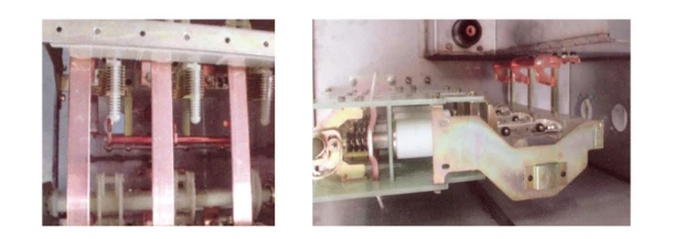
The load switch adopts a coaxial rotary double-break point method. Functional operation is achieved through the cooperation of a single operating hole and a sliding plate. Therefore, the switch can only be in one of three states-"Closed, Open, Grounded"-at any given moment, completely avoiding misoperation.
Pressure Relief Device

The pressure relief device is separated from the cable compartment by a metal plate. If the pressure inside the gas tank becomes too high, the explosion-proof diaphragm inside the device will rupture to release the pressure.
Operating Mechanism
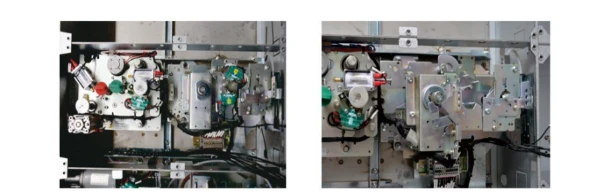
The switch's operating mechanism is installed at the front, outside the gas tank. It undergoes special processing to prevent rust, is convenient for manual operation and maintenance, and can be easily adapted for motorized operation. The operating mechanism can be a spring mechanism or a permanent magnet operating mechanism.
■ The Cable Compartment and Cable Connection Method Truly Meeting Needs
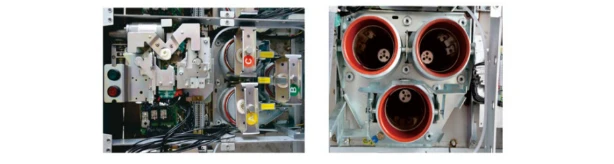
The cable connection compartment is spacious, and the bushings are standard-designed to be compatible with all standard European cable plugs. Under normal conditions, each load switch unit can connect 1-3 outgoing circuits; specially designed models can connect 4-6. Vacuum circuit breaker units can connect 1-2 outgoing circuits.
Standard universal specification bushings (complying with DIN47636 or US standards) are selected to facilitate users in choosing appropriate cable accessories. T-shaped front and rear cable plugs are used for connection. With the European-style stepped bolt tightening structure, M16 bolts connect the front plug and the bushing. Ordinary wiring terminals with heat-shrinkable sleeves are also an optional connection method.

Arrester Connection
The load switch unit can be equipped with a T-shaped rear-plug silicone rubber fully sealed metal oxide surge arrester. When there are many cable circuits and space is insufficient, a π-shaped rear-plug surge arrester can be used.

Fuses
The fuse replacement of the TRC-12 fully enclosed, fully insulated gas-filled RMU is direct and simple. The fuse is placed inside an insulating tube, and the insulating tube is located inside the SF6 metal gas tank.
This design has the following advantages:
◆ The fuse cover and sealing device are located at the point of weakest electrical field.
◆ No conductive materials can adhere to the fuse assembly.
◆ The parts inside the SF6 gas are fully protected.
◆ The fuse cover does not require an additional insulated spring energy storage operating mechanism and a trip linkage device, ensuring that when any phase fuse of the three-phase load switch blows, all three phases automatically open simultaneously.
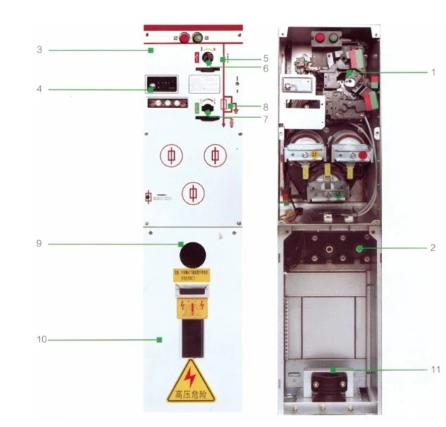
TRC-12 Series Switch Panel Indications
Live line indicator
Main switch operation hole (Operation sequence: Clockwise close / Counter-clockwise open)
Earthing switch operation hole (Operation sequence: Clockwise close / Counter-clockwise open)
Open/Close position indicator (Red indicates closed / White indicates open)
Grounding position indicator
Load switch padlock position
Earthing switch padlock position
C Unit
1. Load Switch Unit C
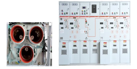
The switch can be a single body, single body with double outgoing bushings, two-unit, three-unit, four-unit, five-unit standard type, or side incoming bushing type. All share a common SF6 gas tank structure, meaning no external busbar connections are required between units, thus simplifying the structure and making it easier to install and safer. Although a single gas tank structure is used, each unit still maintains independent isolation. Units of six and above are connected using insulated busbars to achieve expansion (rear or left/right connection). The cabinet type features standard top-mounted busbar bushings.
2. Standard Configuration
◆ 630A Busbar
◆ Three-position load / Earthing switch
◆ Spring operating mechanism
◆ Load switch and earthing switch open/close position indicators
◆ Outgoing bushings arranged horizontally at the front
◆ Incoming busbar / Busbar voltage indicator (single unit or busbar extension type)
◆ Outgoing voltage indicator
◆ All switch functions can be controlled by adding padlocks on the panel
◆ Interlock between earthing switch and cable compartment door
◆ SF6 pressure gauge
◆ Earthing copper bar
◆ Explosion-proof pressure relief valve
3. Optional Configuration
◆ Short circuit, earthing fault indicator
◆ Measuring ring-type current transformer and ammeter
◆ Metering ring-type current transformer
◆ Switch position key lock
◆ Electric operating mechanism
◆ Permanent magnet operating mechanism
◆ Reserved busbar extension
◆ External busbar
Fuse Replacement Steps
Using the switch operating handle, rotate half a turn counterclockwise, pull outward to remove the fuse for replacement. During installation, align the hook position and rotate clockwise.
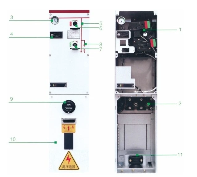
TRC-12 Switch Panel Indications
- Operating mechanism
- Switch incoming bushing
- SF6 pressure gauge
- Live line indicator
- Switch position indicator
- Main switch operation hole
- Earthing switch operation hole
- Grounding position indicator
- Cable compartment observation window
- Cable compartment door
- Cable clamp
F Unit
1. Combination Apparatus Unit
The combination apparatus unit is used for transformer protection with capacities of 1250KVA and below. This unit is equipped with an insulating sleeve that can house a fuse. The insulating sleeve is placed inside the SF6 gas tank to further enhance its insulation performance. When the earthing switch is closed, the lower side of the fuse is grounded, creating a safe isolation between the upper side of the fuse and the power supply, ensuring personnel safety during fuse replacement. To prevent a phase-failure operation of electrical equipment when one phase fuse blows, this unit is configured with a trip linkage mechanism. When the trip observation window shows red, it indicates that the trip device has operated or the fuse has blown and tripped. This unit can be combined with other units to achieve ring main power supply.
2. Standard Configuration
◆ 630A Busbar ◆ Three-position load / Earthing switch ◆ Spring operating mechanism ◆ Load switch and earthing switch open/close position indicators ◆ Outgoing bushings arranged horizontally at the front ◆ Incoming busbar / Busbar voltage indicator (single unit or busbar extension type) ◆ Outgoing voltage indicator ◆ All switch functions can be controlled by adding padlocks on the panel ◆ Interlock between earthing switch and cable compartment door ◆ SF6 pressure gauge ◆ Earthing copper bar ◆ Explosion-proof pressure relief valve
3. Optional Configuration
◆ Short circuit, earthing fault indicator ◆ Measuring ring-type current transformer and ammeter ◆ Metering ring-type current transformer ◆ Switch position key lock ◆ Electric operating mechanism ◆ Permanent magnet operating mechanism ◆ Reserved busbar extension ◆ External busbar
TRC-12-F Switch Panel Indications
- Operating mechanism
- Switch incoming bushing
- SF6 pressure gauge
- Live line indicator
- Switch position indicator
- Main switch operation hole
- Earthing switch operation hole
- Grounding position indicator
- Cable compartment observation window
- Cable compartment door
- Cable clamp
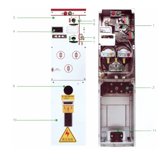
TRC-12-F Switch Panel Indications
Live line indicator
Main switch operation hole (Operation sequence: Clockwise close / Counter-clockwise open)
Earthing switch operation hole (Operation sequence: Clockwise close / Counter-clockwise open)
Open/Close position indicator (Red indicates closed / White indicates open)
Grounding position indicator
Load switch padlock position
Earthing switch padlock position

V Unit
1. Vacuum Circuit Breaker Unit
Uses a spring-operated vacuum circuit breaker with a mechanical life of up to 10,000 times; (The protection operates quickly, with an opening time of no more than 30ms, making it easy to achieve level coordination). A three-position load isolating switch is used. The vacuum circuit breaker and load switch are sealed together in an SF6 gas tank made of 3mm thick stainless steel, making the entire system fully insulated, fully sealed, and maintenance-free.
2. Standard Configuration
◆ 630A Busbar ◆ 630A Circuit Breaker Module ISM ◆ Controller CM (DC24V Operating power supply) ◆ Three-position load isolating switch ◆ External power supply / Self-power supply ◆ Microcomputer-based protection device ◆ Bushing-type protection CT ◆ SF6 pressure gauge ◆ Bushings compliant with DIN47636 standard ◆ Interlock between earthing and cable compartment door ◆ Vacuum circuit breaker position auxiliary contacts: 2NO+2NC ◆ Operating power supply (including PT for power supply, power modules, backup battery)
3. Optional Configuration
◆ Connecting busbar ◆ Measuring current transformer and ammeter ◆ Auxiliary contacts: Load isolating switch position 2NO+2NC, Earthing switch position 2NO+2NC ◆ Permanent magnet mechanism, enabling fast opening and closing of the circuit breaker, used for distribution or incoming switchgear equipment.

TRC-12-V Switch Panel Indications
- SF6 switch gas tank
- Switch incoming bushing
- SF6 pressure gauge
- Live line indicator
- Switch position indicator
- Main switch Open/Close knob
- Circuit breaker energy storage operation hole
- Energy storage position indicator
- Disconnector switch operation hole
- Isolation position indicator
- Earthing switch operation hole
- Circuit breaker operating mechanism
- Isolating / Earthing operating mechanism
- Cable compartment observation window
- Cable compartment door
- Cable clamp
- Earthing busbar
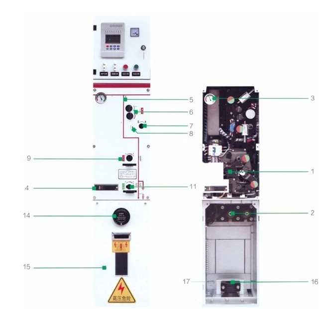
TRC-12-V Switch Panel Indications (Bottom Section)
Live line indicator
Main switch operation hole (Operation sequence: Clockwise close / Counter-clockwise open)
Earthing switch operation hole (Operation sequence: Clockwise close / Counter-clockwise open)
Open/Close position indicator (Red indicates closed / White indicates open)
Grounding position indicator
Load switch padlock position
Earthing switch padlock position

Accessories Overview
- Auxiliary Contacts: All load switches and earthing switches can be equipped with auxiliary contacts to indicate the switch position, installed inside the operating mechanism.
- Remote Control and Telemetry Unit: The TRC-12 solid insulated RMU can be equipped with an integrated remote control and telemetry monitoring unit. This pre-assembled product can be completely assembled at the factory.
- Live Line Indicator: The incoming and outgoing bushings of the switch unit are equipped with capacitive voltage indication devices. Each live line indicator also provides three-phase voltage phase-checking points. Equipped with a phase checker, it can be used for phase alignment.
- Short Circuit / Earth Fault Indicator: To facilitate fault location, the switchgear can be configured with short circuit / earth fault indicators.
- Cable Connection: The TRC-12 solid insulated RMU is equipped with DIN47636 standard bushings. The cable compartment door is interlocked with the earthing switch. Different cable connection units can be selected based on the number of outgoing circuits.
- Pressure Indicating Meter: The TRC-12 solid insulated RMU is equipped with SF6 gas pressure gauges.
- Key Lock: The TRC-12 solid insulated RMU can be configured with key locks for the load switch and earthing switch.
- Control Lock: The TRC-12 solid insulated RMU can be configured with padlocks to prevent operation by unauthorized personnel.
- Secondary Wiring Chamber / Instrument Box: The TRC-12 solid insulated RMU can be configured with a secondary wiring chamber / instrument box for installing secondary accessories and instruments.

Accessories Overview
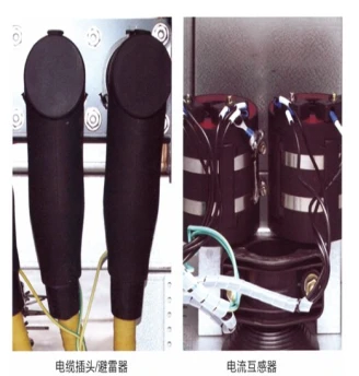
10.Surge Arrester: The TRC-12 solid insulated RMU can be equipped with T-shaped silicone rubber plug-in metal oxide surge arresters.
◆ Continuous operating voltage: 13.6kV
◆ U1mA.DC reference voltage ≥ 25kV
◆ 0.75U1mA.DC leakage current ≤ 50μA
11.Separable Connectors: T-shaped front and rear plugs, PT-shaped plugs. While completing the cable connection, π-shaped plugs for plug-in metal oxide surge arresters can be installed simultaneously.
12.Current Transformer (CT): The TRC-12 solid insulated RMU can be equipped with through-core current transformers as needed for metering / measurement.
◆ Secondary output: 5A
◆ Accuracy class 0.2 or 0.5; The circuit breaker unit adopts a built-in CT.
◆ Epoxy resin casting
◆ Secondary lead-out wire with moisture-proof design
◆ Bushing-type installation
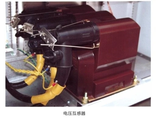
13.Voltage Transformer (PT): The TRC-12 solid insulated RMU can be configured with 10kV fully sealed voltage transformers as needed to meet distribution automation requirements. It can provide signals for metering / measuring voltage, and power supply for the switchgear's electric operating mechanism.
◆ Can be selected as single-phase / three-phase as required.
◆ Ratio: 10/0.1/0.22kV
◆ Accuracy (AC100V): 0.2 or 0.5 class
■ Accessories Overview
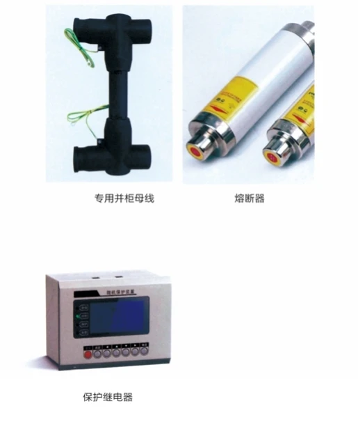
14.Special Busbar for Cabinet Connection: Fully insulated, fully sealed structure.
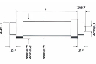
Fuses: Users can configure fuses themselves, or our company can provide recommended configurations based on applicable standards. Our company recommends using HVHRC fuses, which are backup fuses with thermal protection to prevent equipment damage caused by abnormal overheating inside the fuse cylinder. When ordering, please specify the rated capacity of the transformer, operating voltage, and rated current of the fuse.
15.Protection Relay: Adopts a digital self-powered multi-function time-overcurrent protection relay. Compact design, strong environmental adaptability, compliant with standards VDE0435-303, IEC60225, VDE0843.
◆ No external power supply required.
◆ Built-in safe operating mode.
◆ Wide setting range, simple operation steps.
◆ Uses a microprocessor to process signals, achieving high-precision parameter measurement.
◆ Adopts internal self-diagnosis (watchdog) design, reliable operation.
◆ Selectable protection functions.
◆ Definite time overcurrent protection (DMT).
◆ Inverse time overcurrent protection (IDMT).
◆ Optional inverse time curves: standard inverse time, very inverse time, extremely inverse time.

Hot Tags: high voltage gas insulated switchgear, China high voltage gas insulated switchgear manufacturers, suppliers, factory