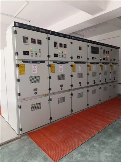

XGN-12HB Environmentally Friendly Gas Filling Cabinet
Overview
The XGN -12 HB type environmentally friendly air-insulated AC metal-enclosed switchgear is an environmentally friendly switchgear developed by our company based on the development trends of the power industry and summarizing years of experience in on-site service, design, and construction of power distribution networks. It aims to provide excellent and environmentally friendly products for China's power distribution networks, and is grounded in the assimilation of domestic and international technologies and design concepts. This product features a reasonable design, reliable power supply, compact structure, convenient installation, flexible operation, small size, and high cost-effectiveness. It is suitable for three-phase AC 50Hz power distribution systems with a rated voltage of 12kV; it is particularly suitable for small secondary substations, switching stations, industrial and mining enterprises, urban residential areas, airports, railways, tunnels, high-rise buildings, and other power systems for receiving and distributing electrical energy.
Suitable locations: power distribution stations and box-type switchgear in load centers such as smart grids, urban power distribution, buildings, and industrial enterprises.
Technical features: Adhering to green and environmentally friendly design concepts and ideas.
Market prospects: Switchgear with little or no SF6 is the future technological trend.

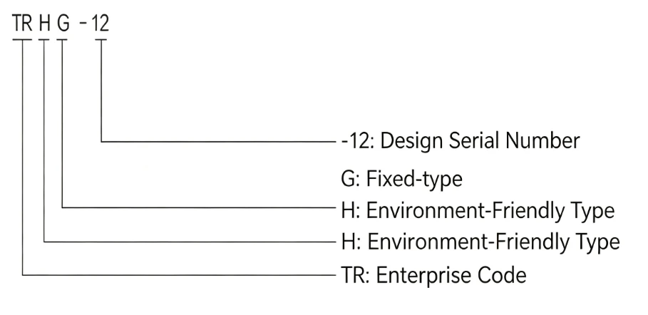
Model Meaning
Normal usage conditions
◆Ambient air temperature: Upper limit +40℃, Lower limit -40℃
◆Humidity: The daily average relative humidity is no more than 95%; the monthly average is no more than 90%.
◆Water vapor pressure: Daily average not exceeding 2.2 kPa; Monthly average not exceeding 1.8 kPa;
◆Altitude not exceeding 3000m.
◆The surrounding air is not significantly polluted by dust, smoke, corrosive and flammable gases, vapors or salt spray.
◆The amplitude of electromagnetic interference induced in the secondary system shall not exceed 1.6kV.
According to the standard
◇ GB 1984 High-voltage AC circuit breakers
◇ GB1985 High-voltage AC disconnect switches and grounding switches
◇ GB 3804 3.6kV~40.5kV High Voltage AC Load Switch
◇ GB 3906 3.6 kV ~40.5 kV AC metal-enclosed switchgear and controlgear
◇ GB4208 Enclosure Protection Rating (IP Code)
◇ Common technical requirements for GB/T11022 standard for high voltage switchgear and controlgear
◇ GB/T16927 1 High Voltage Testing Techniques - Part 1 General Definitions and Test Requirements
◇ DL/T403 Technical Conditions for Ordering 12kV~40.5kV High Voltage Vacuum Circuit Breakers
◇ DL/T404 3.6kV ~40.5kV AC metal-enclosed switchgear and controlgear
◇ DL/T486 High-voltage AC disconnect switches and connecting switches
◇ Common technical requirements of DL/T593 standard for high voltage switchgear and controlgear
◇ JB/T 8144.2 Basic Technical Requirements for Power Cable Accessories with Rated Voltage of 26/35kV and Below: Cable Termination Heads
◇ JB/T 8144.1 General Technical Requirements for Basic Technical Requirements of Power Cable Accessories with Rated Voltage of 26/35kV and Below
Main Technical Parameters
|
Item |
Unit |
Circuit Breaker Unit |
Load Switch Unit |
|
|
Rated Voltage |
kV |
12 |
12 |
|
|
Rated Frequency |
Hz |
50 |
50 |
|
|
Rated Current |
A |
630 |
630 |
|
|
1min Power Frequency Withstand Voltage |
To earth, between phases |
kV |
42 |
42 |
|
Across open contacts |
kV |
48 |
48 |
|
|
Lightning Impulse Withstand Voltage |
To earth, between phases |
kV |
75 |
75 |
|
Across open contacts |
kV |
85 |
85 |
|
|
Rated Short-Time Withstand Current & Duration |
Main circuit |
kA |
20/4s |
/ |
|
Earthing circuit |
kA |
17.4/2S |
/ |
|
|
Rated Peak Withstand Current |
Main circuit |
kA |
50 |
/ |
|
Earthing circuit |
kA |
43.5 |
/ |
|
|
Rated Short-Circuit Making Current (Peak) |
kA |
50 |
50 |
|
|
Rated Short-Circuit Breaking Current |
kA |
20 |
/ |
|
|
Rated Short-Circuit Breaking Operations |
Times |
30 |
/ |
|
|
Rated Operating Sequence |
- |
O-0.3S-CO-180S-CO |
/ |
|
|
Rated Cable / Line Charging Breaking Test |
- |
Class C2 |
/ |
|
|
Single-Phase Earth Fault Breaking Current |
kA |
17.4 |
/ |
|
|
Rated Active Load Breaking Current |
A |
/ |
630 |
|
|
Rated Closed Loop Breaking Current |
A |
/ |
630 |
|
|
Rated Cable Charging Breaking Test |
A |
/ |
10 |
|
|
5% Rated Active Load Breaking Current |
A |
/ |
31.5 |
|
|
Earthing Switch Operating Cycles |
Times |
5 |
5 |
|
|
Loop Resistance |
μΩ |
≤ 140 |
≤ 140 |
|
|
Rated Gas Pressure (20℃ Gauge Pressure) |
MPa |
0.02 |
0.02 |
|
|
Mechanical Life |
Vacuum Switch |
Times |
10000 |
/ |
|
Disconnecting Switch |
Times |
3000 |
/ |
|
|
Earthing Switch |
Times |
3000 |
/ |
|
|
Protection Level |
Enclosure |
- |
IP4X |
IP4X |
|
Gas Tank |
- |
IP67 |
IP67 |
|
|
Operating Power Supply |
V |
AC220/DC220/DC110/DC48/DC24 |
AC220/DC220/DC110/DC48/DC24 |
|
|
Rated Annual Leakage Rate |
% |
≤ 0.1 |
≤ 0.1 |
|
|
Cabinet Dimensions (Single Circuit) |
mm |
420 × 822 × 1420 |
420 × 822 × 1420 |
|
|
Internal Arc Withstand (AFLR) |
kA/s |
20/0.5 |
20/0.5 |
|
|
Dry Air Moisture Content |
ppm |
≤ 150 |
≤ 150 |
Vacuum Switch Mechanical Characteristic Parameters
|
Item |
Unit |
Vacuum Circuit Breaker |
Load Switch Unit |
|
Contact Gap |
mm |
8 ± 1 |
/ |
|
Contact Overtravel |
mm |
3.5 ± 1 |
/ |
|
Average Opening Speed (6mm after opening) |
m/s |
1.2 ± 0.2 |
/ |
|
Average Closing Speed (6mm before closing) |
m/s |
0.8 ± 0.2 |
/ |
|
Contact Bouncing Time on Closing |
ms |
≤ 2 |
/ |
|
Three-Phase Closing Synchronism |
ms |
≤ 2 |
/ |
|
Three-Phase Opening Synchronism |
ms |
≤ 2 |
/ |
|
Closing Time |
ms |
30 - 70 |
≤ 900 |
|
Opening Time |
ms |
18 - 50 |
/ |
|
Phase Center Distance |
mm |
150 ± 1.5 |
/ |
|
Contact Bouncing Amplitude on Opening |
mm |
≤ 1.5 |
/ |
|
Contact Over-travel on Opening |
mm |
≤ 2 |
/ |
|
Rated Contact Pressure |
N |
1600 ± 160 |
1100 ± 100 |
Main Technical Parameters and Characteristic Parameters of Isolating and Earthing Switches
|
Item |
Unit |
Isolating Switch |
Earthing Switch |
|
Rated Voltage |
kV |
12 |
/ |
|
Rated Frequency |
Hz |
50 |
/ |
|
Rated Current |
A |
630 |
/ |
|
1min Power Frequency Withstand Voltage |
To earth, between phases |
kV |
42 |
|
Across open contacts |
kV |
48 |
|
|
Lightning Impulse Withstand Voltage |
To earth, between phases |
kV |
75 |
|
Across open contacts |
kV |
85 |
|
|
Rated Short-Time Withstand Current & Duration |
kV |
20/4s |
/ |
|
Rated Peak Withstand Current |
kV |
50 |
/ |
|
Mechanical Life |
Times |
3000 |
/ |
|
Contact Pressure |
N |
160 ± 20 |
/ |
|
Manual Closing Operating Force |
N |
≤ 200 |
/ |
|
Manual Opening Operating Force |
N |
≤ 200 |
/ |
|
Static and Moving Contact Gap |
mm |
≥ 100 |
100 |
|
Phase Center Distance |
mm |
150 ± 1.5 |
/ |
|
Earthing Switch Closing Synchronism |
ms |
/ |
≤ 2 |
Features of the new air-insulated vacuum ring main unit
Independent enclosed air box structure
The medium-voltage live parts are installed in a closed stainless steel enclosure with an IP67 protection rating, which absolutely guarantees the personal safety of operators; it is not affected by small animals, corrosive gases, humidity, condensation, dust and sunlight, and will not rust or cause eddy currents (the cabinet is made of 304 stainless steel).
1. Dry air insulation
Using dry air as the insulating medium makes the product more environmentally friendly, eliminating the use of SF6 gas and its pollution to the environment. The medium-pressure part inside the gas box adopts a composite insulation structure, which is compact, small in size, safe and reliable, and practical.
2. Design of a small vacuum interrupter
The miniaturized vacuum interrupter chamber structure, which uses vacuum as the arc-extinguishing medium and features low contact pressure, reduces the closing output power of the operating mechanism, improves the operational reliability and mechanical life of the switchgear, and truly achieves 10,000 maintenance-free cycles.
3. High level of personal safety
The switchgear adopts a fully insulated and fully sealed structure design, with the enclosure protection level reaching IP4X and the medium-voltage live parts protection level reaching IP67. The switchgear and transmission cables are connected with touchable, fully shielded pluggable cable heads. It has a reliable pressure relief device and mechanical and electrical "five-proof" interlocking. The human-machine interface is well-maintained to prevent misoperation and ensure the personal safety of operators.
4. Spacious cable connection room
The cable connection compartment has a large connection space, suitable for parallel cable connections and additional surge arrester cable connection plugs at the same height. Cables can be installed parallel to each other. The center of the cable outlet bushing is 650mm from the bottom of the box.
5. Flexible expansion methods
Top- or side-mounted electrical connectors can be designed between the functional units to reliably connect with other functional units and facilitate expansion.
6. Each functional unit can be designed as a unit or a shared enclosure, with a maximum of 4 units per enclosure.
The ring main unit's casing, air box, pressure relief device, and operating mechanism have the following advantages
1. Outer shell
The overall structure is bolted together and is made of high-quality steel plate or aluminum-zinc coated steel plate.
The upper part of the outer casing is the secondary instrument compartment, the middle part is the switch operating mechanism compartment, and the lower part is the cable compartment. The lower part of the cable compartment has a cable inlet and a sealed bottom sealing plate. The cable compartment door is a pull-type door, which is simple and convenient to operate and is mechanically interlocked with the switch operating mechanism.
2. Air box
The switch operating mechanism, gas pressure gauge, cable inlet and outlet sleeves, and pressure relief device are made of high-quality 304 stainless steel plate and welded and processed, and are arranged on the gas box.
3. Pressure relief device
The pressure relief device is installed at the bottom of the gas chamber. When the pressure inside the gas chamber rises abnormally and exceeds the predetermined value, the pressure relief device will be activated to release the pressure, prevent the accident from escalating, and protect the safety of personnel and equipment.
4. Operating mechanism
The operating mechanism is installed in the compartment outside the switch room. The disconnect switch and grounding switch use independent three-position operating mechanisms; a mechanical interlock is installed between the two operating handholes to prevent misoperation.
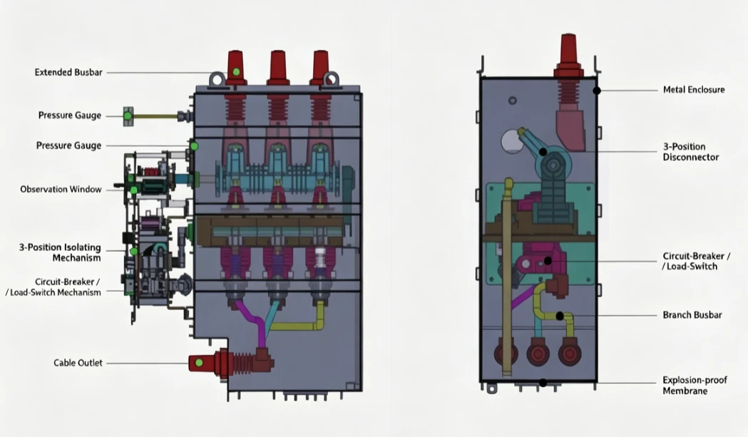
Standard Cabinet-type Structure (Upper Isolation & Upper Earthing Scheme)

Internal Structure of Standard Cabinet-type (Upper Isolation & Upper Earthing Scheme)
Unit Cabinet Selection
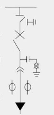
Selection Instructions for Circuit Breaker Unit - V Unit
① The V Unit (circuit breaker unit cabinet) has left extension, top extension, and right extension, corresponding to the abbreviations +V, V+, and V+ respectively.
② The V Unit can be combined with other units in a common cabinet, with a maximum of 4 units per cabinet.
③ If connecting with third-party unit cabinets, please provide the external dimensions, the positions of the connection points, and the connection methods of the mating cabinet.
④ Please indicate whether the extension positions are for backup or immediate use.
⑤ During selection, please provide a single-line diagram of the primary scheme and the component configuration list.
Selection Instructions for Load Switch Unit - C Unit
① The C Unit (load switch unit cabinet) has left extension, top extension, and right extension, corresponding to the abbreviations +C, C+, and C+ respectively.
② The C Unit can be combined with other units in a common cabinet, with a maximum of 4 units per cabinet.
③ If connecting with third-party unit cabinets, please provide the external dimensions, the positions of the connection points, and the connection methods of the mating cabinet.
④ Please indicate whether the extension positions are for backup or immediate use.
⑤ The standard load switch operating mechanism does not have pre-charging capability and closes directly; however, it can be modified to include a pre-charging function.
⑥ During selection, please provide a single-line diagram of the primary scheme and the component configuration list.

Selection Instructions for Potential Transformer Unit - PT Unit
① The PT Unit (voltage transformer unit cabinet) has left extension, top extension, and right extension, corresponding to the abbreviations +PT, PT+, and PT+ respectively.
② The PT Unit can be combined with other units in a common cabinet, with a maximum of 4 units per cabinet.
③ If connecting with third-party unit cabinets, please provide the external dimensions, the positions of the connection points, and the connection methods of the mating cabinet.
④ Please indicate whether the extension positions are for backup or immediate use.
⑤ Please provide the technical parameters of the PT (voltage transformer) and the high-voltage fuse.
⑥ During selection, please provide a single-line diagram of the primary scheme and the component configuration list.

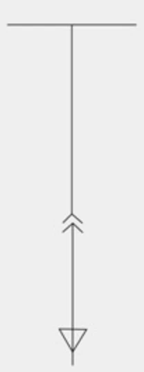
Selection Instructions for Riser Unit - D Unit
The D Unit (riser unit cabinet) has left extension, top extension, and right extension, corresponding to the abbreviations +D, D+, and D+ respectively.
② The D Unit can be combined with other units in a common cabinet, with a maximum of 4 units per cabinet.
③ If connecting with third-party unit cabinets, please provide the external dimensions, the positions of the connection points, and the connection methods of the mating cabinet.
④ Please indicate whether the extension positions are for backup or immediate use.
⑤ During selection, please provide a single-line diagram of the primary scheme and the component configuration list.
Operating Mechanism Selection
This switchgear uses a spring operating mechanism. Both the circuit breaker unit mechanism and the load switch unit mechanism can be operated electrically or manually. The three-position manual operating mechanism is used for the isolating switch and the earthing switch. The circuit breaker operating mechanism has an energy storage function, whereas the load switch operating mechanism closes directly without pre-charging. Typically, the circuit breaker mechanism or load switch mechanism is installed on the same mounting plate as the three-position mechanism (isolating switch and earthing switch) and features reliable mechanical and electrical interlocking. They can also be installed separately, but in that case, the interlocking system would need to be custom-designed.
Mechanism Model Definition

Mechanism Outline Diagram

Main Technical Parameters for Circuit Breaker Unit or Load Switch Unit Mechanism
|
Item |
Unit |
Data |
|
Motor Energy Storage Voltage |
V |
AC220/DC220/DC110/DC48/DC24 |
|
Coil Operating Voltage (Closing / Opening) |
V |
AC220/DC220/DC110/DC48/DC24 |
|
Overcurrent Trip Current |
A |
5 / 3.8 |
|
Secondary Circuit Power Frequency Withstand Voltage |
V |
2500 |
|
Mechanism Output Angle |
° |
19° |
|
Mechanism Output Closing Work (Torque) |
J |
65 / 50 |
|
Mechanism Oil Buffering Stroke |
mm |
13 |
Main Technical Parameters for Isolating & Earthing Three-Position Mechanism
|
Item |
Unit |
Data |
|
Mechanism Output Angle (Isolating / Earthing) |
° |
65° / 55° |
Selection Instructions for Operating Mechanisms
① Please specify the mechanism model.
② Please specify the operating voltages for energy storage, closing, and opening.
③ Please specify whether an overcurrent trip coil is required and its trip current value.
④ For any special requirements, please contact our company's technical personnel.
Gas Tank
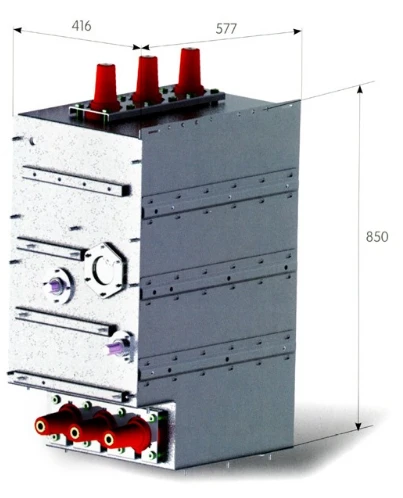
Our company provides 304 stainless steel gas tanks. The welding employs mold positioning and fully automatic robotic welding, ensuring minimal deformation, high precision, and excellent consistency. The external dimensions of several standard gas tank models commonly used by our company are as follows (customized designs for special requirements must be communicated with our technical personnel). The gas tank outline is shown in the figure.

Transport, Loading/Unloading, Acceptance & Storage
Transportation and Loading/Unloading
1.The switchgear shall be transported with the circuit breaker or load switch in the "Open" position, its energy storage device in the "Released" state, and the earthing switch in the "Closed" state.
2.The external packaging of the switchgear shall have anti-vibration, moisture-proof, and dust-proof capabilities, and be suitable for railway and road transportation.
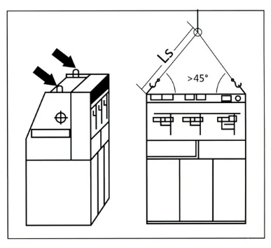
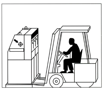
3.When handling the switchgear using manual pallet jacks or freight forklifts, it should be placed on a transport pallet. If a crane is used for lifting, the crane hook should be attached to the four lifting rings at the top of the switchgear, and the angle between the lifting rope and the top of the cabinet must be greater than 45° to avoid deformation of the cabinet body or the lifting ears.
4.During the loading and unloading of the RMU, operations should be carried out according to the storage and handling instructions marked on the packaging box to prevent cargo damage accidents. The switchgear should generally be moved vertically to avoid tilting or overturning.
5.If damage is discovered after the RMU has been transported over long distances, the freight forwarding department should be notified immediately to confirm the damage accident.
Acceptance and Storage
1.Visual Inspection: After receiving the goods, users should promptly open the box and check whether the equipment has any damage or deformation during transportation.
2.Gas Pressure Check: The product has been filled with dry gas at the factory. The gas pressure is approximately 0.02MPa. On-site inspection mainly involves judging whether the gas pressure is normal through the indication of the gas density gauge (green indicates normal, red indicates abnormal).
3.Accessory Inspection: After opening the box, promptly check whether the primary scheme of the equipment meets the ordering requirements, and whether the accessories such as factory documents, dedicated opening tools, and spare parts are complete. If there are any discrepancies, please contact our company promptly.
4.Storage: If the equipment cannot be installed immediately and needs to be stored for a period of time after unboxing, it should be promptly re-packaged with the original packaging and stored in a dry and clean place to avoid mechanical damage to the equipment.
Installation, Use & Maintenance
Installation
1.Before putting the RMU into operation, carefully check whether the rated voltage and rated current of each operating component match the actual situation, and operate using the opening and closing methods of the mechanism to check whether all indicators are correct.
2.During product installation, the cabinet must not be flipped or tilted. Anti-vibration measures should be taken. When lifting, it should be lifted horizontally. Refer to the installation drawing for the specific installation method. The bottom of the switchgear cabinet is connected to the metal foundation frame using bolts to secure the switchgear onto it (there should be 4 connecting surfaces between the cabinet body and the frame). The connecting screws and bolts are of specification M10, with a torque of 40±4Nm.
3.Operators should have a basic understanding of the performance, installation, adjustment, and maintenance knowledge of the RMU and its controller. Problems occurring during operation should be recorded and, if necessary, the manufacturer should be notified.

Maintenance
1.Daily Inspection: The patrol inspection cycle of the RMU is determined by the user based on actual conditions.
lCheck whether the RMU shell is damaged.
lCheck whether the load switch positions are correct.
lCheck whether the indicator lights and live line indicators are correct.
lCheck whether the gas pressure is within the specified range.
lCheck whether the RMU grounding is in good condition.
lCheck whether the RMU foundation is sunken or uneven.
■ Regular Maintenance:
Under normal conditions, the maintenance and servicing cycle of the switchgear is generally three years. Specific maintenance measures should be carried out as follows:
According to the installation and use manual, tighten all electrical connections (cables, meters, etc.).
Use a vacuum cleaner to clean all components (operating mechanism, cable compartment, meter compartment, etc.) for visual inspection.
Perform one closing/opening operation on all switches, including the earthing switch.
Clean the cable compartment.
For accumulated dust and greasy dirt, a cloth dampened with a small amount of alkaline cleaner can be used. Rinse clean with clean water, and finally wipe the surface dry with a dry cloth.
Acceptance requirements: All components should be intact without obvious discharge traces or damage to connection joints, and no obvious overheating traces at the contact surfaces. If any non-compliant components are found, they should be replaced.
Factory Delivery List
The following materials and accessories are provided with the product at the time of delivery (valid for unit cabinets or mechanisms):
- Product installation and operation manual.
- Product factory test report and certificate of conformity.
- Packing list.
- Operating handle.
- Keys.
Ordering Instructions
- Users Main circuit wiring scheme number, main circuit diagram, layout diagram, and plane layout diagram.
- Secondary circuit schematic diagram.
- Models, specifications, quantities, and drilling diagrams of all electrical components in the switchgear cabinet.
- Summary of electrical equipment.
- If the switchgear is used under special environmental conditions, please specify.
- If other accessories, extra components, or spare parts are required, please specify the types and quantities.
Hot Tags: environmentally friendly gas switchgear, China environmentally friendly gas switchgear manufacturers, suppliers, factory, draw out switchgear unit, Electric Traction Substation, ggd fixed distribution panel, high voltage fixed contactor, XGN17 40 5 assembly, yb 12 pre installed substation