
Overview
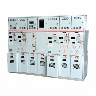
The MNS type low-voltage withdrawable switchgear (hereinafter referred to as switchgear) is a low-voltage withdrawable switchgear product developed by our company, based on the foreign MNS series low-voltage switchgear and incorporating comprehensive improvements. It is currently one of the leading low-voltage withdrawable switchgear products in China. This product consists of standardized and serialized modules, and its drawers are equipped with reliable mechanical locking devices, making it safer and more reliable for users.
This switchgear is suitable for three-phase five-wire power supply systems with AC 50(60)Hz, rated voltages of 400V, 660V, and rated currents of 5000A and below. It can be used for power generation, substations, industrial enterprises, high-rise buildings, airports, docks, broadcasting and television communication centers, etc., for power generation, power distribution, power conversion, and control of energy-consuming equipment. It can also perform reactive power compensation on its main busbar through capacitor compensation cabinets. It complies with the national standard: GB7251.1 "Low-voltage switchgear and controlgear assemblies" and IEC60439 "Low-voltage switchgear and controlgear assemblies".

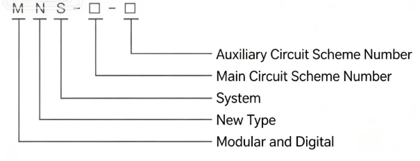
Model Meaning
Normal Service Conditions
◆ The surrounding air temperature must not be higher than +40℃ and not lower than -5℃, with the average temperature within 24 hours not exceeding +35℃.
◆ The relative humidity of the surrounding air must not exceed 50% at a maximum temperature of +40℃. Higher relative humidity is allowed at lower temperatures (e.g., 90% at +20℃), but consideration should be given to the possibility of moderate condensation due to temperature changes.
◆ For indoor use, the altitude of the installation site must not exceed 2000m.
◆ It should be installed in locations free from severe vibration and impact, and where electrical components are not subject to corrosion.
Main Technical Parameters
|
No. |
Item |
Technical Parameters |
|
1 |
Overvoltage category |
IV III |
|
2 |
Pollution degree |
3 |
|
3 |
Rated operating voltage (Ue)(V) |
400/660 |
|
4 |
Rated insulation voltage (Ui)(V) |
660/1000 |
|
5 |
Rated frequency (Hz) |
50(60) |
|
6 |
Horizontal busbar - Rated current |
≤ 5000A |
|
7 |
Horizontal busbar - Rated short-time withstand current (Icw)(kA) |
50, 65, 80 (1s RMS value) |
|
8 |
Horizontal busbar - Rated peak withstand current (Ipk)(kA) |
105, 140, 176 (0.1s peak value) |
|
9 |
Vertical busbar - Rated maximum working current |
≤ 1000A |
|
10 |
Vertical busbar - Rated short-time withstand current |
50kA |
|
11 |
Vertical busbar - Rated peak withstand current |
105kA |
|
12 |
Enclosure protection class |
IP30, IP40 (special conditions) |
Products Description
This switchgear adopts imported technology and has been technically improved based on its original design to better suit China's national conditions. The cabinet body uses a C-type profile with a 25mm modulus. By connecting these profiles through connectors, various cabinet structures and drawer units meeting various needs are formed. In the MCC cabinet, high-strength flame-retardant engineering plastic components are used, making its safety performance more reliable. At the same time, the imported functional panels have been modified and combined using a 200mm modulus, making it more favorable for the design requirements of mixed cabinet assembly of PC cabinets and MCC cabinets. The drawer units and the cabinet body have a reliable interlocking device to prevent load-pulling under live conditions, thereby improving safety. Additionally, the cabinet body is generally made of cold-rolled steel plates and assembled after passivation treatment, or galvanized steel plates can be used according to different user needs.
■ Types of Switchgear
◇ Incoming cabinet and Bus-tie cabinet: Various types of domestic and foreign frame circuit breakers, such as RMW1, CW1, NA1, DW45, CDW7, MT, E, and other series, are used as the main switch to achieve incoming and bus-tie functions.
◇ Power Center cabinet (PC): Various types of domestic and foreign frame circuit breakers, such as DW45, NA1, CDW7MT, E, and other series, are used for power distribution.
◇ Motor Control Center (MCC): It is composed of small drawer units. The main switch for each branch circuit uses molded case circuit breakers with high breaking capacity or rotary fuse-switch disconnectors for load switches.
◇ Reactive power compensation cabinet.
■ Drawer Types
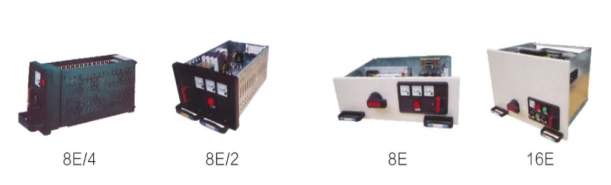
There are five sizes based on the 8E (200mm) height, adopting a modular structural design. The effective component installation height is 1800mm, making the overall cabinet layout more reasonable and aesthetically pleasing.
8E/4: Height 200 × Width 150 × Depth 400. Accommodates 4 drawer units in parallel in the vertical space.
8E/2: Height 200 × Width 300 × Depth 400. Accommodates 2 drawer units in parallel in the vertical space.
8E: Height 200 × Width 600 × Depth 400. Accommodates 1 drawer unit in the vertical space.
16E: Height 400 × Width 600 × Depth 400. Accommodates 1 drawer unit in the vertical space.
24E: Height 600 × Width 600 × Depth 400. Accommodates 1 drawer unit in the 24E (600mm) height space.
The above five drawer types can be assembled individually or in mixed combinations within a single cabinet (see Figure 1).
Drawer Type and Maximum Quantity Table
|
Drawer Type |
8E/4 |
8E/2 |
8E |
16E |
24E |
|
Max. Number of Units |
36 |
18 |
9 |
4+8E |
3 |
Cabinet Body Introduction
◇ Basic dimensions of the cabinet body
Table: Incoming cabinet and Bus-tie cabinet
|
Main Busbar Transfer Cabinet |
Incoming Cabinet & Bus-tie Cabinet |
|
|
Height (mm) |
2200 |
2200 |
|
Width (mm) |
400 |
600, 800, 1000 |
|
Depth (mm) |
800, 1000 |
800, 1000 |
|
Remarks |
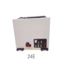
Table: Power Center (PC) Cabinet
|
2 Breakers |
3 Breakers |
|
|
Height (mm) |
2200 |
2200 |
|
Width (mm) |
800, 1000 |
800, 1000 |
|
Depth (mm) |
800, 1000 |
800, 1000 |
|
Remarks |
DW45-2000 and below, with the same current capacity but smaller volume compared to similar circuit breakers. |
DW45-2000 and below, with the same current capacity but smaller volume compared to similar circuit breakers. |
Table: Motor Control Center (MCC) Cabinet and Capacitor Compensation Cabinet
|
MCC Cabinet |
Capacitor Compensation Cabinet |
|||
|
Height (mm) |
2200 |
2200 |
||
|
Width (mm) |
600 |
800 |
1000 |
600, 800, 1000 |
|
Depth (mm) |
1000, 800 |
1000, 800 |
1000, 800, 600 |
800, 1000, 600 |

◆ Cabinet compartment design
MNS cabinets can be configured as single-front operation cabinets or double-front operation cabinets according to requirements. Each cabinet is fixedly divided into three compartments: the main busbar compartment, the apparatus compartment, and the cable compartment. (See Figure 2 for details).
◇ Safety protection system
Each cabinet is equipped with a flame-retardant high-density polyurethane plastic functional panel, or a painted galvanized partition board, installed between the main busbar compartment and the apparatus compartment. Its function is to effectively prevent arcing and short circuits between the busbars caused by component failures, thereby making the operation safer.
Between the upper and lower drawer compartments, there are galvanized metal bottom plates with ventilation holes for isolation. This provides strong isolation between adjacent circuits.
Various plastic components are used inside the cabinet to support live parts. These components are required to be halogen-free and have a CTI300 level of tracking resistance.
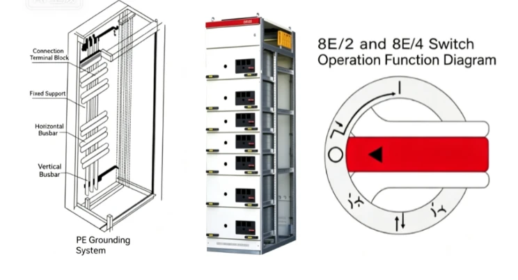
The cabinet is equipped with an independent PE grounding system and N neutral conductor, both running through the entire device. Each branch circuit grounding or neutral connection point can be connected nearby. The entire busbar system installation is shown in Figure 3. The frame structure components are connected using self-tapping screws and have high grounding reliability. (See Figure 3 for details).
◆ Busbar system
The horizontal busbars of the switchgear are arranged in the horizontal busbar isolation compartment and can be placed at the rear or top of the cabinet. In cabinets with rear-outlet structure, the horizontal busbars are located at the cabinet top. The power distribution busbars (vertical busbars) are assembled in flame-retardant plastic functional panels, which can not only prevent discharge caused by arcing but also prevent human contact. They are connected to the main busbars via connection pieces.
◆ Electrical and Mechanical Interlocking of Drawers
The drawer unit has a reliable mechanical interlocking device, controlled by the operating handle, with clear positions for opening, closing, testing, drawing out, and isolating. To strengthen safety protection, padlocks can be added to the operating handle in the fixed position, with a maximum of three locks.
◆ Rear-outlet Switchgear Structure
Rear-outlet cabinets can reduce the layout width of the switchgear row. In rear-outlet switchgear, the main busbars are installed horizontally at the top of the cabinet, and the rear half of the cabinet is the cable compartment, where incoming and outgoing cables are connected. The front of the switchgear is the device compartment, installing the functional units of the switchgear equipment. This system design moves the cable compartment from the side wall to the rear of the cabinet, greatly reducing the layout width of the switchgear to further meet the layout requirements of substation space.
The feeder cabinet has a width of 600mm and a depth of 1000mm, with an isolated main busbar compartment at the top and a device compartment below. The effective installation height of the front device compartment is 72E (E=25mm), isolated from the rear cable compartment by functional panels. This makes full use of the switchgear installation space, with a compact structure and flexible unit configuration. The rear cable compartment has a door, making installation and maintenance convenient.
The width of the incoming cabinet can be selected based on the frame current of the incoming unit, with recommended widths of 400, 600, 800, 1000mm, and a cabinet depth of 1000mm.

Circuit Components Selection
The components in the device mainly use technical indicators that are advanced or manufactured using imported technologies that can already be mass-produced domestically.
a. For main circuit breakers of 630A and above and incoming/outgoing circuits, the DW45 series, NA1 series, AE series, CW series, or RMW series are primarily selected. Imported MT series, E series, or IZM series can also be used.
b. For feeder circuits and motor control circuits of 630A and below, the CDM1 series, CM1 series, TM30 series, NM1 series, RMM1 series are primarily selected. The imported NS series, S series, or NZM series molded case circuit breakers can also be used.
c. AC contactors mainly use CDC7, LC1 series, 3TB series, CJX2 series contactors, as well as their matching thermal relays and interlock mechanisms.
d. Current transformers use BH series, SDH series, LMK series, etc.
e. Fuses use RT series or NB series with high breaking capacity.
Table 1
|
Main Busbar Transfer |
Item |
Tolerance (mm) |
|
1 |
Verticality |
3.3 |
|
2 |
Horizontality |
Adjacent cabinet tops: 2 |
|
3 |
Flatness |
Adjacent cabinet edges: 1 |
|
4 |
Gap between cabinets |
2 |
Installation and Use
Upon arrival at the receiving site, first check whether the packaging is intact and undamaged. If problems are found, notify the relevant contract department promptly to make business records, jointly analyze the causes, and properly handle evidence and after-sales matters. For products that are not installed immediately, they should be placed in appropriate locations and properly preserved according to the normal service conditions and the temporary storage regulations for electrical equipment.
◆ Installation of the product should be carried out according to the installation diagram 5. Foundation channel steel and bolts used for bolt fixing should be provided by the user. When connecting the main busbar, if the surface is uneven due to transportation or storage, it should be flattened before reconnecting and tightening.
◆ Whether installed individually or in rows, the verticality, cabinet surface flatness, and gap between cabinets should meet the requirements of Table 1.
◆ Inspection and testing before commissioning after installation
◇ Check whether the cabinet surface paint or other covering materials (e.g., spray coating) are damaged, whether the inside of the cabinet is dry and clean, and whether the installation screws of various components are loose.
◇ Whether the operating mechanisms of electrical components are flexible, without sticking or excessive operating force.
◇ Whether the opening and closing of main electrical components are reliable and accurate.
◇ The drawer or withdrawable mechanism should slide smoothly, lightly, without jamming or collision.
◇ The centerlines of the moving and fixed contacts of the drawer or withdrawable structure should be aligned, and the contact should be tight. The insertion depth of main and auxiliary contacts should meet requirements. The mechanical interlock or electrical interlock device should act correctly, and the locking or unlocking should be reliable.
◇ Drawers with identical primary schemes, secondary principles, and drawer sizes should be able to be interchanged conveniently without jamming or collision.
◇ When replacing fuse links, they should meet the requirements of the engineering design.
◇ The setting values of protection should be correctly set according to actual loads.
◇ Use a 1000V megohmmeter to measure the insulation resistance, which must not be less than 10MΩ.
◇ The connection of all busbars should be good, and insulating supports, mounting parts, and other accessories should be installed firmly and reliably.
◆ Precautions for use
◇ The equipment is a low-voltage distribution cabinet installed without leaning against the wall, with front operation and double-sided maintenance. The maintenance passage and cabinet doors must only be entered or operated by professionally qualified personnel for operation, inspection, and maintenance.
◇ After connecting the cables, the bottom of the switchgear should be sealed to prevent small animals from crawling into the cabinet and causing short circuits.
◇ After multiple openings and closings, especially after short-circuit opening and closing, air circuit breakers and molded case circuit breakers may cause local burning of contacts and generate carbonaceous substances, which increases contact resistance. Maintenance and repair should be carried out according to the circuit breaker's instruction manual.
◇ After installation and maintenance, the isolation conditions between compartments and functional units must be strictly checked to ensure the good functional separation of the device and prevent the expansion of faults.
◆ Operation of Drawers
◇ Operation of 8E/2 and 8E/4 drawers
MNS cabinets are equipped with dedicated operating mechanisms for 8E/2 and 8E/4 drawers. Through an operating handle installed on the drawer panel, the functions of opening, closing, testing, isolation, and locking of the switch can be realized within a 360° rotation range. The operating mechanism is also equipped with a micro switch for electrical interlocking.
|
Position |
Description |
|
I Working position |
Main switch closed, main circuit and control circuit connected, functional unit locked. |
|
O Opening position |
Main switch open, control circuit connected, functional unit locked. |
|
↑ Testing position |
Main switch open, main circuit disconnected, control circuit connected, functional unit locked. |
|
↓ Withdrawing position |
Main circuit and control circuit disconnected. Drawer can be pulled out or pushed in. |
|
↑ Isolation position |
Drawer pulled out 30mm. Main circuit and control circuit isolated, drawer locked. |
Operation handle can be moved from "O" position to "I" position only after being pressed inward. The operating handle can be padlocked at the opening, testing, and isolation positions for safety protection. A maximum of three padlocks can be added.
Working process: At the withdrawing position (↓), the drawer can be pushed in or pulled out. After pushing the drawer in, rotate the operating handle counterclockwise by 45°, pull out 30mm to reach the "↑" isolation position. At the withdrawing position (↓), after pushing the drawer in, rotate the operating handle clockwise by 45° to reach the "↑" testing position. Continue clockwise rotation by 45° to reach the main switch "O" position. Press the handle down 6mm and rotate clockwise by 90° to close the switch. To exit, perform the reverse operations.

b. Operation of 8E, 16E, 24E drawers
The MNS cabinet 8E and above drawer panels are equipped with mechanism operating handles and switch operating handles. Through the coordination of the mechanism operating handle and the switch operating handle, functions of opening, closing, testing, isolation, and locking are realized. The switch operating handle realizes the opening/closing operation of the switch (disconnector or molded case circuit breaker), and the mechanism operating handle realizes the drawer position, such as testing, withdrawing, isolation, and working positions.
Hot Tags: general electric low voltage switchgear, China general electric low voltage switchgear manufacturers, suppliers, factory, Fixed Switchgear, GZDW-panel, High Voltage Switchgear and Controlgear, integrated hybrid switchgear substation, jxf terminal box, Outdoor Grid connected PV Cabinet