
Application
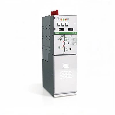
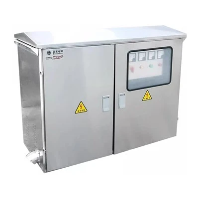
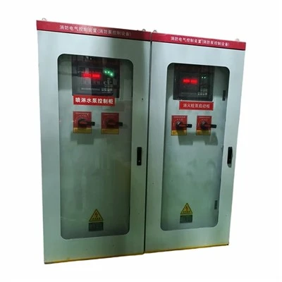
GCS series low-voltage withdrawable switchgear is suitable for power distribution systems in industries such as power plants, petroleum, chemical, metallurgical, textile, and high-rise buildings. In places with high automation levels, such as large power plants and petrochemical systems, where computer interfaces are required, it serves as a low-voltage complete power distribution device for power distribution, centralized motor control, and reactive power compensation in power generation and supply systems with three-phase AC frequencies of 50(60)Hz, rated working voltages of 400V and 660V, and rated currents up to 5000A and below.
The design of the device complies with the following standards: IEC439-1 "Low-voltage switchgear and controlgear assemblies" and GB7251 "Low-voltage switchgear and controlgear assemblies".

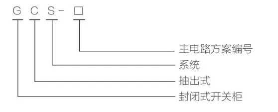
Model Meaning
Normal Service Conditions
◇ The ambient air temperature must not be higher than +40℃ and not lower than -5℃, with the average temperature within 24 hours not exceeding +35℃. If exceeded, derated operation is required based on actual conditions.
◇ For indoor use, the altitude of the installation site must not exceed 2000m.
◇ The relative humidity of the ambient air must not exceed 50% at a maximum temperature of +40℃. Higher relative humidity is allowed at lower temperatures (e.g., 90% at +20℃). The potential influence of condensation due to temperature changes should be considered.
◇ The inclination of the device relative to the vertical plane should not exceed 5° during installation, and the entire set of cabinet rows should be relatively level (complying with the GBJ232-82 standard).
◇ The device should be installed in locations free from severe vibration and impact, and free from conditions that could cause undue corrosion to electrical components.
◇ Special requirements from users can be resolved through negotiation with the manufacturer.
Main Technical Parameters
Basic technical parameters are shown in Table 1:
|
No. |
Item |
Parameter |
|
1 |
Main circuit rated voltage (V) |
AC 400/660 |
|
2 |
Auxiliary circuit rated voltage |
AC 220, 380(400), DC 110, 220 |
|
3 |
Rated frequency (Hz) |
50(60) |
|
4 |
Rated insulation voltage (V) |
660 |
|
5 |
Rated current (A) - Horizontal busbar |
≤ 5000 |
|
Rated current (A) - Vertical busbar (MCC) |
1000 |
|
|
6 |
Busbar rated short-time withstand current (KA/1s) |
50, 80 |
|
7 |
Busbar rated peak withstand current (KA/0.1s) |
105, 176 |
|
8 |
Power frequency test voltage (V/1min) - Main circuit |
2500 |
|
Power frequency test voltage (V/1min) - Auxiliary circuit |
2000 |
|
|
9 |
Busbar - Three-phase four-wire system |
A.B.C.PEN |
|
Busbar - Three-phase five-wire system |
A.B.C.PE.N |
|
|
10 |
Protection level |
IP30, IP40 |
Main Circuit Schemes
The main circuit schemes of the GCS cabinet consist of a total of 32 groups and 118 specifications, excluding derived schemes and specifications arising from changes in the control and protection of auxiliary circuits. It covers the needs of power generation, power supply, power consumption, and other power users. The rated operating current is 5000A, and it is suitable for distribution transformers of 2500kVA and below. In addition, capacitor compensation cabinets are designed for the need to improve the power factor of power supply and consumption, and reactor cabinets are designed considering the comprehensive investment needs.
Auxiliary Circuit Schemes
The GCS auxiliary circuit diagram manual contains a total of 120 auxiliary circuit schemes, divided into two volumes (upper and lower). The upper volume, "AC Operation Section", contains 63 schemes in total. The lower volume, "DC Operation Section", contains 57 schemes in total. The auxiliary circuit schemes of the DC operation section are mainly used for the low-voltage plant (station) power systems of power plants and substations. It is suitable for low-voltage plant power systems of units with capacities of 200MW and below, as well as 300MW and above, including general control methods for working (standby) power incoming lines, power feeder lines, and motor feeder lines.
The auxiliary schemes of the AC operation section are mainly used for low-voltage systems in substations of industrial and mining enterprises and high-rise buildings. There are 6 combination schemes suitable for dual-power operation control. It is also equipped with electrical interlocking, standby automatic switching, and automatic reset control circuits, which can be directly adopted in engineering designs.
DC control power supplies are DC 220V or 110V, while AC control power supplies are AC 380V or 220V, forming complete sets of cabinets composed of drawer units. The 220V control power supply is led from the public control power supply supplied by a dedicated control transformer in the cabinet. The public control power supply uses a non-grounding control transformer, and a 24V power supply is reserved for use when weak current signal lights are needed.
For details on the installation location of watt-hour meters, the method of introducing voltage signals, and other installation and usage requirements, please refer to the "Compilation Instructions" of the auxiliary circuit diagrams.
Main Busbar
To improve the dynamic and thermal stability of the busbars and improve the temperature rise of the contact surfaces, all equipment uses TMY-T2 series hard copper bars. The copper bars are fully tin-plated, or fully silver-plated copper busbars may also be selected.
◇ Horizontal busbars and vertical busbars are installed separately in the busbar isolation compartments within the cabinet.
◇ The neutral grounding busbar uses a hard copper bar. It penetrates the horizontal neutral grounding line (PEN) or grounding + neutral line (PE+N).
Selection of Electrical Components
GCS cabinets mainly select electrical components with advanced technology, stable performance, and high indicators, which are mass-produced domestically using imported technologies.
◇ Main switch
For power incoming and feeder switches of 630A and above, the DW45 series is primarily selected, but DW48 series, AE series, 3WE, or ME series can also be selected. If necessary, imported M series or F series can also be chosen.
◇ Molded case switches for feeders and motor controls below 630A primarily select TG series, CM1 series, NM series, CDM series, TG30 series, and other molded case switches.
◇ To improve the dynamic stability of the main circuit, GCS series dedicated combined busbar clamps and insulating supports are designed, made from high-strength, flame-retardant synthetic materials by thermal molding. They have high insulation strength, good self-extinguishing properties, and a unique structure.
◇ To reduce the temperature rise of partition boards, plugs, and cable terminals of functional units, GCS dedicated adapters are designed. The adapters have large capacity and low temperature rise.
◇ If the design department selects new types of electrical components with superior performance and advanced technology according to user needs, due to the good versatility of the GCS series cabinets, replacing electrical components will not cause difficulties in manufacturing and installation.
Dimensions (Table)
|
Item |
Values |
||
|
Cabinet Height (H) |
2200 mm |
||
|
Cabinet Width (D) |
400 / 600 / 800 / 1000 mm |
||
|
Cabinet Depth (W) |
800, 1000 / 800, 1000 / 600, 800, 1000 / 600, 800, 1000 mm |
||
|
No. |
Item |
Tolerance (mm) |
|
|
1 |
Verticality |
3.3 |
|
|
2 |
Horizontality |
Adjacent cabinets (top): 2 |
|
|
3 |
Flatness |
Adjacent cabinets (edge): 1 |
|
|
4 |
Gap between cabinets |
2 |
|
Installation and Use
Upon arrival at the receiving site, first check whether the packaging is intact and undamaged. If problems are found, notify the relevant contract department promptly to make commercial records, jointly analyze the causes, and properly handle evidence and after-sales matters. For products that are not installed immediately, they should be stored properly in suitable locations according to the normal service conditions and the interim storage regulations for electrical equipment.
◆ The installation of the product should be carried out according to the installation schematic diagram. The foundation channel steel and the bolts used for bolt fixing should be provided by the user. When connecting the main busbars, if the surface is uneven due to transportation or storage, it needs to be leveled before reconnecting and tightening.
◆ Whether installed individually or in rows, the verticality, surface flatness of the cabinets, and the gap between cabinets should meet the requirements of Table 3.
◆ Inspection and testing before commissioning after installation
◇ Check if the cabinet paint or other covering materials (e.g., spray coating) are damaged, and whether the inside of the cabinet is dry and clean.
◇ Whether the operating mechanisms of electrical components are flexible, without sticking or excessive operating force.
◇ Whether the opening and closing of main electrical components are reliable and accurate.
◇ The drawer or withdrawable mechanism should slide smoothly, lightly, without jamming or collision.
◇ The centerlines of the moving and fixed contacts of the drawer or withdrawable structure should be aligned, and the contact should be tight. The insertion depth of main and auxiliary contacts should meet requirements. The mechanical interlock or electrical interlock device should act correctly, and the locking or unlocking should be reliable.
◇ Drawers with identical primary schemes, secondary principles, and drawer sizes should be able to be interchanged conveniently without jamming or collision.
◇ When replacing fuse links, they should meet the requirements of the engineering design.
◇ The setting values of protection should be correctly set according to actual loads.
◇ Use a 1000V megohmmeter to measure the insulation resistance, which must not be less than 10MΩ.
◇ The connection of all busbars should be good, and insulating supports, mounting parts, and other accessories should be installed firmly and reliably.
◆ Precautions for use
◇ The equipment is a low-voltage distribution cabinet installed without leaning against the wall, with front operation and double-sided maintenance. The maintenance passage and cabinet doors must only be entered or operated by professionally qualified personnel for operation, inspection, and maintenance.
◇ After multiple openings and closings, especially after short-circuit opening and closing, air circuit breakers and molded case circuit breakers may cause local burning of contacts and generate carbonaceous substances, which increases contact resistance. Maintenance and repair should be carried out according to the circuit breaker's instruction manual.
◇ After installation and maintenance, the isolation conditions between compartments and functional units must be strictly checked to ensure the good functional separation of the device and prevent the expansion of faults.
Operation of Drawers
■ 1/2 Drawer operation
The operating mechanism of this drawer consists of rotating parts, a shaft, a latch, etc., and provides functions for switching (opening/closing), testing, isolation, and locking. The operating mechanism is also equipped with a micro switch for electrical interlocking.
- Working position: Main switch is closed, main circuit and control circuit are both connected, functional unit is locked.
- Opening position: Main switch is open, control circuit is connected, functional unit is locked.
- Test position: Main switch is open, main circuit is disconnected, control circuit is connected, functional unit is locked.
- Isolation position: Drawer is pulled out by 30mm. Main and control circuits are isolated, drawer is locked.
- Withdrawal position: Main circuit and control circuit are both disconnected, drawer can be withdrawn arbitrarily.
- The operating handle can only be turned from the (O) position to the (I) position after being pressed down by 6mm.
- Working process: At the withdrawal position (↓), the drawer can be pushed in or pulled out. Rotate counterclockwise by 45°, and when pulling out the drawer, it will automatically reach the isolation position (↑). Rotate clockwise by 45° to reach the test position (↑). Rotate clockwise by another 45° to reach the opening position (O). Press the handle down by 6mm and rotate clockwise by 90° to close the switch. To exit, perform the reverse operations.
- If necessary, a padlock can be applied to the operating handle at the opening, test, and isolation positions of the main switch for safety protection.
■ Operation of 1 unit and above drawers
The operating mechanism of this drawer consists of a shaft, cylindrical cam, clutch plate, pin compression spring, fork, etc. By rotating the cylindrical cam with the operating handle, the drawer can be plugged or unplugged, providing functions for opening, closing, testing, isolation, and locking of the switch.
Working position: Main switch is closed, main circuit and control circuit are both connected, functional unit is locked.
Opening position: Main switch is open, control circuit is connected, functional unit is locked.
Test position: Main switch is open, main circuit is disconnected, control circuit is connected, functional unit is locked.
Isolation position: Drawer is pulled out by 30mm. Main and control circuits are isolated, drawer is locked.
Withdrawal position: Main circuit and control circuit are both disconnected, drawer can be withdrawn arbitrarily.
The operating handle can only be turned from the (O) position to the (I) position after being pressed down by 9mm.
Working process: At the withdrawal position (↓), the drawer can be screwed in or out. Rotate the operating handle clockwise by 30° to reach the isolation position (↑), then rotate clockwise by 180° to reach the test position (↑). Continue rotating clockwise by 30° to reach the opening position (O). Press the handle down by 9mm and rotate clockwise by 90° to close the main switch. To exit, perform the reverse operations.
If necessary, a padlock can be applied to the operating handle at the opening, test, and isolation positions of the main switch for safety protection.

■ Unlocking Mechanism
There is a red plastic button at the lower right corner of the drawers of 1 unit and above. This is the unlocking mechanism. When the operating mechanism fails, during maintenance, or when it is necessary to open the drawer, turn the operating handle to the "O" position, then press the red plastic button downward to open the door.
Hot Tags: low tension switchgear, China low tension switchgear manufacturers, suppliers, factory, ggd electrical enclosure, Hermetically-sealed-enclosure, Low and Medium Voltage Switchgear, snyb 12 integrated pv, yb 12 intelligent substation, zgs 12 unit substation