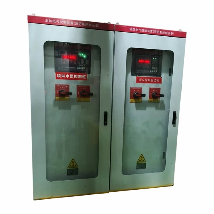
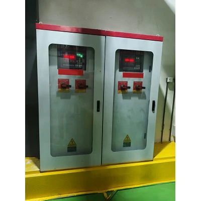
Fire pump control cabinet product manual (star-delta start, with mechanical emergency manual control)
Product Overview
This series of fire pump control cabinets are dedicated fire protection electrical control devices , strictly designed and manufactured in accordance with "GB 16806-2006 Fire Linkage Control System" and "GB 50974-2014 Technical Specification for Fire Water Supply and Fire Hydrant System". They are specifically designed for use with fire hydrant pumps, sprinkler pumps, pressure-stabilizing pumps, and other fire pumps. The equipment adopts a star-delta reduced-voltage starting method , is equipped with a dedicated intelligent fire controller, and comes standard with both electrical manual and mechanical emergency manual pump start functions . It possesses a full range of functions including automatic linkage, remote control, fault protection, status monitoring, and emergency forced pump start, making it a core control device for building fire water supply systems.
The products are widely used in various fire protection engineering projects such as commercial complexes, residential communities, factories, office buildings, and public buildings. They support multiple control modes, including one-on-one standby and two-on-one standby, and are stable in operation, with complete protection and compliance with fire protection acceptance standards. They can effectively ensure the reliable start and stop of fire pumps under fire conditions and meet the mandatory requirements for fire emergency water supply.
Model Meaning
XF - KB - Y/△ - □
- XF: Firefighting equipment
- KB: Control Cabinet
- Y/△: Star-delta reduced voltage starting method
- □: Compatible with water pump power (15KW/22KW/30KW/45KW/55KW/75KW, etc.)

Main Technical Parameters
|
Serial Number |
Technology Projects |
Parameter Indicators |
|
1 |
Rated operating voltage |
AC380V/50Hz Three-phase four-wire |
|
2 |
Controlling motor power |
15KW~160KW (standard power for star-delta adapter) |
|
3 |
Startup method |
Star-delta (Y/Δ) step-down automatic switching start |
|
4 |
Startup time |
3–15 seconds (adjustable with controller) |
|
5 |
Starting current |
One-third of the full-voltage start-up effectively reduces the impact on the power grid. |
|
6 |
Control Mode |
Three modes: automatic, electrical manual, and mechanical emergency manual. |
|
7 |
Work schedule |
Short-time work system (uninterrupted operation for fire protection only) |
|
8 |
Protection function |
Overload, short circuit, phase loss, undervoltage, overvoltage, and phase sequence error protection. |
|
9 |
Linkage Method |
Passive contact linkage of fire alarm control panel, linkage of fire hydrant button, linkage of pressure switch |
|
10 |
Communication function |
Standard RS485 interface, capable of uploading operation and fault signals to the fire control room. |
|
11 |
Protection level |
IP30 (for indoor fire pump rooms) |
|
12 |
Work environment |
Temperature -10℃~+55℃, humidity ≤95% with no condensation |
Core Structure and Functional Description
■ Star-Delta Reduced Voltage Starting System (Core Starting Unit)
This control cabinet adopts a standard star-delta reduced voltage starting circuit , consisting of a main contactor, a star starting contactor, a delta running contactor, a thermal overload relay, and a time delay control unit. It is the preferred starting method for medium and high power fire pumps and fully meets the requirements for low-impact and high-reliability starting of fire pumps.
Working principle : In the initial stage of equipment startup, the controller controls the motor windings to operate in a star (Y) connection , reducing the motor terminal voltage to 1/3 of the rated voltage, greatly reducing the starting current and avoiding the impact of large starting current on the power grid, burning out the lines and switching equipment; after the motor speed stabilizes and startup is completed, it automatically switches to a delta (△) connection after a delay to run at full speed and rated capacity, ensuring that the water pump reaches the rated head and flow rate to meet the fire extinguishing water supply needs.
Key advantages : Smooth start-up, low current, low failure rate, high cost performance, no harmonic interference issues of soft start devices, suitable for fire protection conditions requiring long-term standby and emergency start; the start-up delay time can be freely adjusted by the controller to adapt to the start-up characteristics of water pumps with different power.
■ Intelligent fire protection controller (core control unit)
The cabinet is equipped with a dedicated intelligent controller for fire pumps , which serves as the core of the equipment's brain. It automatically controls the pump's start-up, shutdown, switching, protection, and signal transmission throughout the entire process. Unlike ordinary industrial controllers, it has dedicated fire-fighting logic to prevent automatic pump shutdown and malfunctions, thus meeting mandatory fire safety regulations.
Core features :
1. Three-mode intelligent switching : It integrates three working modes: automatic, electrical manual, and emergency manual. The mode switching is interlocked to prevent conflict and misoperation, and it is suitable for various scenarios such as daily inspection, automatic linkage, and fire emergency.
2. Fully automatic fire alarm linkage : It can receive signals from the fire alarm control panel, fire hydrant buttons, sprinkler pressure switch, flow switch, and passive switch. Upon receiving a fire alarm signal, it automatically starts the fire pump to achieve linkage operation of the fire protection system.
3. Improved fault protection and memory : Real-time monitoring of faults such as power phase loss, phase sequence error, overload, short circuit, and motor overheating. When a fault occurs, the machine will stop immediately, sound and light alarms will be activated, and the fault code will be locked. It has a built-in fault memory storage function to facilitate operation and maintenance troubleshooting and prevent operation with faults.
4. Automatic rotation between main and backup pumps (optional): Dual-pump models support automatic rotation between the main and backup pumps and automatic switching in case of failure. When the main pump fails, the backup pump will start running instantly, ensuring uninterrupted water supply throughout the process.
5. Remote signal upload : Real-time upload of operation, stop, fault, and manual/automatic status signals to the fire control room to achieve remote monitoring and centralized management.
6. Fire-fighting dedicated logic lock : The pump is prohibited from automatically stopping after a fire starts . It can only be manually reset to stop, which fully complies with fire protection regulations and prevents the water pump from stopping unexpectedly during fire fighting.
■ Emergency manual activation system (mandatory for fire protection)
This equipment strictly complies with fire protection acceptance standards and is equipped with dual emergency start functions of electrical manual and mechanical emergency manual . This solves the fatal hidden danger of pump failure due to controller failure, secondary circuit damage, or signal failure, and ensures that the water pump can be started 100% under extreme fire conditions.
- Panel Electrical Manual Mode
For routine inspections and general emergency scenarios, switch the panel knob to the "manual" position and directly control the water pump's start and stop via the panel's start and stop buttons. This allows for manual intervention in the equipment's operation, making it suitable for daily debugging, periodic inspections, and troubleshooting. It is simple to operate and safe and controllable.
- Mechanical Emergency Manual Mode (Forced Emergency)
This is the highest priority emergency function for fire protection. Independent of the controller and secondary control circuits, it features a purely mechanical structure, requires no electrical control or signals, and is unaffected by component failures. When the intelligent controller in the control cabinet burns out, secondary circuits malfunction, the PLC fails, or the remote signal fails, but the main power supply is normal, maintenance personnel can use a dedicated mechanical emergency handle on the cabinet to forcibly close the main circuit contactor , bypassing the star-delta delayed start stage and directly forcibly starting the fire pump at full speed. This ensures absolutely reliable emergency water supply during fires and is a core, mandatory function for fire safety inspections.
Emergency operation priority : Mechanical emergency manual > Electrical manual > Automatic linkage
■ Overall Structure and Protection Design
The cabinet is made of thickened cold-rolled steel plate with electrostatic powder coating, making it rust-proof, corrosion-resistant, sturdy, and durable. Internal components are modularly laid out, with main and control circuits wired separately, separating strong and weak current circuits, ensuring neat wiring and good heat dissipation. The equipment is equipped with power indicator lights, running indicator lights, a fault audible and visual alarm, and a mode display window, providing a clear overview of the equipment status. The electrical circuits are equipped with both electrical and mechanical interlocks, eliminating the risk of phase-to-phase short circuits caused by star-delta contactors, ensuring extremely high operational safety.
Scope of Application
1. Control of indoor fire hydrant pumps, automatic sprinkler pumps, and fire pressure stabilizing pumps in various buildings;
2. Fire water supply systems for commercial complexes, office buildings, hospitals, schools, residential communities, and industrial plants;
3. Fire water supply control systems that require star-delta reduced-voltage start, automatic linkage, and mechanical emergency pump start;
4. Newly built or renovated fire protection projects that meet the national fire protection acceptance requirements.
Installation and Usage Instructions
■ Installation Environment Requirements
1. The equipment is installed in a dedicated fire pump room, which is well-ventilated, dry, free of dust, corrosive gases, and flammable and explosive materials;
2. The cabinet should be installed vertically to the ground, securely fixed, away from water pump vibration sources, and with sufficient space for maintenance.
3. Reliable grounding with a grounding resistance ≤4Ω ensures equipment and personnel safety;
4. The ambient temperature should be controlled between -10℃ and +55℃. Outdoor installation is prohibited from being exposed to rain or direct sunlight.
■ Installation and Wiring Steps
1. Secure the equipment in place, complete the cabinet grounding, and check that the cabinet is undamaged, components are intact, and wiring is secure;
2. Connect to a three-phase 380V main power supply, distinguish between live wire, neutral wire, and ground wire, and ensure the wiring is firmly secured and properly insulated.
3. Connect the water pump motor load line, strictly follow the star-delta wiring specifications for corresponding wiring, and prevent incorrect phases and loose connections;
4. Connect the fire alarm linkage signal line, feedback signal line, and RS485 communication line, ensuring accurate wiring;
5. Pre-power-on inspection: Confirm that all switches are in the open position and that there are no short circuits or grounding faults in the circuit;
6. Power on and test each stage to ensure that the automatic linkage, manual start/stop of electrical circuits, star-delta switching, fault protection, and mechanical emergency functions are all normal.
■ Operating Procedures for Working Mode
1. Automatic mode (daily duty mode)
When the panel knob is switched to the "Automatic" position, the equipment is in 24-hour fire protection duty mode. After receiving fire alarm signals from the fire control panel, pressure switch, and fire hydrant button, it automatically completes star-delta reduced pressure start-up, and the water pump is put into fire water supply; in case of failure, it automatically alarms and automatically switches between main and backup pumps, and the entire process is unattended.
2. Electrical manual mode (inspection and commissioning mode)
Switch the panel knob to the "manual" position to disable the automatic linkage function. Manually control the water pump operation via the start/stop button on the panel. This is only for daily inspections, equipment debugging, and fault repair. Do not leave it in manual mode for extended periods during normal operation.
3. Mechanical emergency manual mode (extreme fire emergency mode)
Use only in case of fire or electrical control system failure. Open the emergency operation window on the cabinet, operate the dedicated mechanical handle to force the main circuit to engage, and directly start the water pump at full speed. After the fire is extinguished, manually reset the handle, disconnect the power, and troubleshoot and repair any equipment malfunctions. Unauthorized operation is strictly prohibited in non-emergency situations .
Maintenance and Care
1. Daily inspection: Check the status of power supply, operation and fault indicator lights every day to confirm that the equipment is in automatic monitoring mode, with no alarms, no abnormal noises and no overheating;
2. Monthly maintenance: Conduct manual start-stop tests to verify that the star-delta start-up switching is smooth and without jamming, and that the audible and visual alarms and signal feedback functions are normal; tighten the wiring terminals and clean the dust inside the cabinet;
3. Quarterly maintenance: Test the fire alarm linkage function and the main/standby pump switching function, verify the accuracy of phase loss and overload protection actions, and check the flexibility of mechanical emergency handle operation;
4. Annual maintenance: Comprehensive testing of contactors, relays, controllers, and thermal relays; replacement of aging components; and simulation of fire safety acceptance testing by powering on the entire unit.
5. It is strictly forbidden to alter the control program, adjust the protection parameters, or short-circuit the protection circuit without authorization. It is also strictly forbidden for non-professionals to operate the mechanical emergency device.
Troubleshooting Common Faults
|
Fault phenomenon |
Cause of the fault |
processing method |
|
Pump cannot start in automatic mode |
Linkage signal not connected, controller parameters abnormal, secondary circuit disconnected. |
Inspect the fire alarm control circuit, reset the controller parameters, and repair the secondary control circuit. |
|
Water pump start-up error, phase loss protection |
Three-phase power supply phase loss, loose wiring, motor winding fault, contactor contact damage. |
Troubleshoot the incoming power supply, tighten the terminals, repair or replace the faulty contactor, and test the motor's operating condition. |
|
Star-delta switching lag, startup failure |
Inappropriate start-up delay parameters, star contactor failure, poor circuit contact |
Adjust the controller startup delay, repair or replace the faulty contactor, and troubleshoot the wiring. |
|
Overload alarm shutdown |
Excessive water pump load, mechanical jamming, and insufficient thermal relay parameters. |
Troubleshoot mechanical faults in the water pump, reset and properly adjust the parameters of the thermal relay. |
|
The controller has no display and the whole machine is not working. |
Damaged power supply, blown fuse, controller malfunction |
Replace the control fuse, repair the control power supply, and inspect or replace the controller. |
Safety Precautions
1. Equipment installation, commissioning, maintenance, and troubleshooting must be performed by certified electricians and fire protection professionals, and electrical safety and fire protection regulations must be strictly followed.
2. When the equipment is powered on, it is strictly forbidden to open the cover and touch the live parts, and live maintenance and rewiring operations are strictly prohibited;
3. Mechanical emergency start is a dedicated function for fire emergencies. It is strictly forbidden to operate it casually in daily life to avoid safety accidents caused by accidental start-up of the equipment under load.
4. Fire pumps are dedicated firefighting equipment and must not be used for any other purpose. It is also strictly forbidden to shut down or disable the control cabinet without authorization.
5. When repairing equipment, the main power supply must be disconnected and work must be carried out only after the circuit is completely de-energized to prevent electric shock from residual voltage.
6. Regularly test emergency functions to ensure that the equipment can be reliably started at any time in the event of a fire.
Product Warranty
This product is manufactured and inspected in strict accordance with national fire protection standards and electrical specifications. Before leaving the factory, it undergoes a full range of tests, including power-on testing, linkage testing, startup performance testing, and protection function testing, to ensure it meets quality standards. The product has an 18-month warranty period. During the warranty period, the manufacturer will repair or replace parts free of charge for malfunctions not caused by human error or force majeure. Malfunctions caused by unauthorized modification, improper operation, human damage, or abnormal use in harsh environments are not covered by the warranty.
Hot Tags: fire pump control cabinet, China fire pump control cabinet manufacturers, suppliers, factory, Electric Traction Substation, gas insulated ring main unit, High-frequency-switching, Integrated-disconnector-earthing-switch, low voltage junction box, Power Generation Grid connection Cabinet