
35KV Prefabricated Substation Product Manual
Product Overview
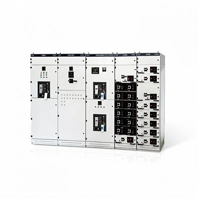
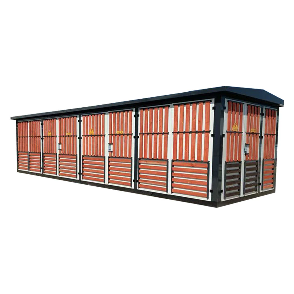
- A 35kV prefabricated substation (referred to as a 35kV box-type substation) is a prefabricated complete set of power distribution equipment that organically combines high-voltage power receiving, transformer voltage reduction, and low-voltage power distribution functions. This product adopts a "three-compartment" structure design, consisting of three independent functional units: a 35kV high-voltage compartment , a transformer compartment , and a low-voltage distribution compartment. It integrates high-voltage switchgear, power transformers, and low-voltage power distribution devices into one unit, and has the advantages of compact structure, convenient installation, reliable operation, and convenient maintenance.
- Our products are widely used in photovoltaic power generation, wind power generation, industrial and mining enterprises, residential communities, commercial centers, municipal engineering and other fields, and are especially suitable for the step-up grid connection system of new energy power plants.
Implementation Standards and Usage Conditions
■ Implementation Standards
GB/T 17467-2020 Prefabricated High-Voltage/Low-Voltage Substations
GB 3906-2020 3.6kV~40.5kV AC Metal-Enclosed Switchgear and Controlgear
GB 7251.1-2013 Low-voltage switchgear and controlgear assemblies
NB/T 10204-2019 Technical Requirements for Low-Voltage Grid-Connected Interface Devices for Distributed Photovoltaic Power Generation
■ Normal operating conditions
|
Project |
Technical Requirements |
|
Ambient temperature |
-25℃ to +40℃, with a 24-hour average not exceeding +35℃. |
|
Altitude |
≤2000m (reduced capacity required for applications exceeding this limit) |
|
relative humidity |
Daily average ≤95%, monthly average ≤90% |
|
earthquake resistance |
Earthquake intensity 8 degrees |
|
Installation site |
There is no risk of fire or explosion, and there is no serious pollution, chemical corrosion, or violent vibration. |
Overall Structure and Layout
Three-room independent structural designThis product adopts a three-chamber layout in the shape of "目" or "品" , with each chamber completely isolated by steel plates and having an independent door to ensure operational safety.
■ Schematic diagram of floor plan
【Eye-shaped layout (recommended)】
Layout features:
The high-voltage compartment and the low-voltage compartment are located on opposite sides, with the transformer in the middle.
Each room has its own door, ensuring no interference between them.
Optimal ventilation and heat dissipation
Sufficient space for inspection and maintenance
■ Cabinet structural parameters
|
Project |
Parameter |
|
External dimensions (length × width × height) |
5500×2500×2800mm (customizable) |
|
Box material |
2.5mm high-quality cold-rolled steel sheet/galvanized steel sheet |
|
Surface treatment |
Phosphating + electrostatic powder coating, RAL7035/Military Green |
|
Protection level |
IP54 (enclosure) / IP2X (indoor spaces) |
|
Insulation layer |
50mm thick rock wool insulation layer |
|
ventilation system |
Natural ventilation + forced cooling fan |
35KV High Voltage Chamber
■ Main Functions
Receiving and distributing 35kV high-voltage electrical energy
High-voltage side overcurrent, short circuit, overvoltage, and undervoltage protection
On/off control of the high-voltage side of the transformer
Lightning overvoltage protection
Live indicator and forced interlock
■ Standard Configuration
|
Equipment Name |
Model Specifications |
Quantity |
|
Vacuum circuit breaker |
ZN63-40.5/630-31.5kA |
1 unit |
|
disconnect switch |
GN22-40.5/630A |
Group 1 |
|
Grounding switch |
JN15-40.5/31.5kA |
Group 1 |
|
Current transformer |
LZZBJ9-35, transformer ratio based on capacity |
3 |
|
Voltage transformer |
JDZ9-35, 35/√3 : 0.1/√3 |
3 |
|
Zinc oxide surge arrester |
HY5WZ-51/134 |
3 |
|
Microcomputer protection device |
Integrated line/transformer protection and control system |
1 set |
|
live display |
DXN-35kV, with interlocking |
1 set |
Technical Parameters
|
Rated voltage |
40.5kV |
|
Rated current |
630A / 1250A |
|
Rated short-circuit breaking current |
25kA / 31.5kA |
|
Rated short-time withstand current (4s) |
25kA / 31.5kA |
|
Rated lightning impulse withstand voltage |
185kV (to ground) / 215kV (break point) |
|
Rated power frequency withstand voltage (1 min) |
95kV (to ground) / 118kV (break point) |
Transformer Room
■ Main Functions
The 35kV high-voltage power is reduced to 0.4kV low-voltage power.
Power conversion and electrical isolation
Temperature monitoring and overheat protection
Forced air cooling
■ Transformer Selection (Standard Configuration)
|
Project |
Oil-immersed transformer (S13/ S20 ) |
Dry-type transformer (SCB1 8 ) |
|
Rated capacity |
800kVA ~ 10000kVA |
|
|
Voltage combination |
35 ± 2×2.5% / 0.4kV |
|
|
Connection group |
D,yn11 |
|
|
Impedance voltage |
6.5% ~ 8% |
|
|
Insulation class |
Grade A |
H-class |
|
Cooling method |
ONAN/ONAF |
AN/AF |
|
Temperature control protection |
Oil surface temperature controller |
Platinum resistance temperature controller |
■ Auxiliary Configuration of Transformer Room
- Temperature control system : Intelligent temperature controller, over-temperature alarm, over-temperature trip, automatic fan start/stop.
- Cooling system : 4 axial flow fans, forced ventilation and heat dissipation
- Lighting system : explosion-proof lighting fixtures, door control switches
- Fire protection system : smoke detectors, heat detectors
- Oil-immersed special-purpose : oil level gauge, pressure relief valve, gas relay
Low-voltage power distribution room
■ Main Functions
Distribution and control of 0.4kV low-voltage power
Low-voltage side overload, short circuit, and leakage protection
Reactive power compensation (optional)
Electricity metering and data acquisition
Grid connection interface and anti-islanding protection (dedicated to photovoltaic/wind power)
■ Standard Configuration
|
Functional Unit |
Main Equipment |
illustrate |
|
incoming line cabinet |
Intelligent frame circuit breaker ACB |
Rated current is based on transformer capacity, breaking capacity 50kA |
|
Outgoing line cabinet |
Molded Case Circuit Breaker (MCCB) |
4-8 rounds of play, configured as needed. |
|
Capacitor compensation cabinet |
Intelligent capacitor + reactor |
Compensation capacity 30% of transformer capacity, switching accuracy ≤1kvar |
|
Metering cabinet |
0.2S-class multi-functional energy meter |
Forward and reverse metering, supports 485 communication |
|
Grid-connected cabinet (optional) |
Anti-islanding protection device + grid-connected circuit breaker |
Over/under voltage protection, high/low frequency protection, and reverse power protection. |
■ Technical Parameters
- Rated operating voltage : AC 400V
- Rated frequency : 50Hz
- Rated current of main busbar : 1600A ~ 4000A
- Rated short-time withstand current (1s) : 50kA / 65kA / 80kA
- Power factor : ≥0.95 after compensation
- Protection rating : IP30
Secondary Control System
Microprocessor-based protection : The high-voltage side is equipped with a transformer/line integrated protection device, which has instantaneous overcurrent, overload, zero-sequence, overvoltage, and undervoltage protection.
Intelligent monitoring : The low-voltage side is equipped with intelligent measurement and control instruments to monitor parameters such as voltage, current, power, energy, and harmonics in real time.
Communication functions : Supports RS485/Modbus and Ethernet communication, and can be connected to SCADA systems or cloud platforms.
Temperature control linkage : The transformer temperature is linked to the cooling fan, and over-temperature automatic alarm and tripping occurs.
Access control system : Optional electronic access control system that records door opening operations.
Installation and Debugging
Foundation construction : Pour concrete foundation according to drawings, and reserve grounding electrode.
Equipment placement : hoist the entire unit to the foundation, adjusting the levelness to ≤2mm/m.
Grounding connection : The main grounding grid of the enclosure is reliably connected, and the grounding resistance is ≤4Ω.
Cable connections : High-voltage cables, low-voltage cables, and control cables should be connected according to phase sequence.
Insulation test : High voltage side ≥1000MΩ, low voltage side ≥10MΩ
Protection setting : Set the microcomputer protection parameters according to system requirements.
Power-on test : Power on in stages to verify that each function is normal.
Grid connection acceptance : Cooperate with the power supply department to complete grid connection testing and acceptance.
Maintenance and Care
|
Maintenance cycle |
Maintenance Project |
|
Routine inspection (daily) |
Visual inspection, instrument readings, temperature monitoring, abnormal sounds |
|
Monthly inspection |
Terminal fastening, switch status, fan operation, grounding check |
|
Quarterly maintenance |
Cleaning and dust removal, insulation testing, and protection function verification. |
|
Annual maintenance |
Comprehensive inspection, oil sample testing (oil transducer), and protective transmission test. |
Ordering Instructions
- Specify the transformer capacity, connection group, and impedance voltage.
- Define the main wiring scheme of the high-voltage switchgear and the circuit breaker parameters.
- Provide the number of low-voltage outgoing circuits and the current requirements for each circuit.
- Indicate whether reactive power compensation is required and the compensation capacity.
- For new energy projects, please specify grid connection requirements and protection configurations.
- Please specify any special environmental requirements (high altitude, extreme cold, high humidity, etc.).
- Please specify any special requirements regarding the color, material, or dimensions of the enclosure.
- Please provide detailed specifications for communication protocols and monitoring system requirements.
- This product has passed ISO9001 quality system certification, and all components comply with the national 3C certification standard.
Hot Tags: smart substation in smart grid, China smart substation in smart grid manufacturers, suppliers, factory, 12 KV Substation, automated power substation, fixed pattern hv panel, GZDW-panel, high voltage fixed contactor, Integrated-disconnector-earthing-switch