Overview
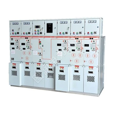
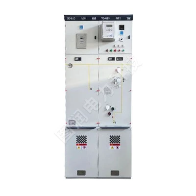
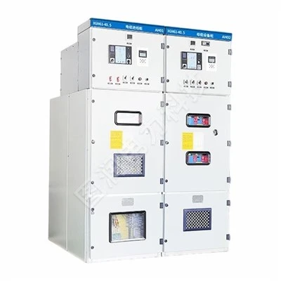
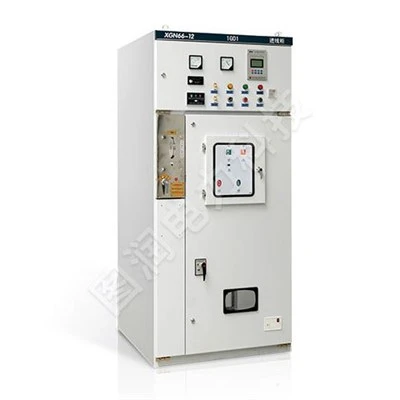
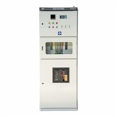
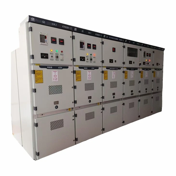
The KYN28A-12 type indoor AC metal-clad centrally mounted switchgear is suitable for three-phase AC power systems with a rated voltage of 12kV and a rated frequency of 50Hz. It is used to receive and distribute electrical energy and to control, protect, and monitor circuits.
Meet the standards:
- GB3906-2006 3.6~40.5kV AC Metal-Enclosed Switchgear and Controlgear
- GB11022-89 General Technical Requirements for High Voltage Switchgear
- IEC 298 (1990) - Metal-enclosed switchgear and controlgear for AC applications with rated voltages of 1 kV and up to 50 kV
- DL404-97 Technical Specifications for Ordering Indoor AC High-Voltage Switchgear

Functions and features
The switchgear is designed according to the armored metal-enclosed switchgear standards in GB3906-91. It consists of two main parts: the cabinet and the centrally located withdrawable unit (i.e., the trolley) (see figure). The cabinet is divided into four separate compartments, with an enclosure protection rating of IP4X, and an IP2X rating when the doors of each compartment and the circuit breaker compartment are open. It features overhead and cable entry/exit options, and can be arranged and combined to form a complete power distribution system. This switchgear can be installed, commissioned, and maintained from the front; therefore, it can be installed back-to-back, in double arrangements, or against a wall, improving safety, flexibility, and reducing floor space.
Shell and others
The main cabinet frame of the switchgear is made of aluminum-zinc coated thin steel plate, machined by CNC machine tools, and employs a multi-folding edge process. This gives the entire cabinet not only high precision and strong corrosion and oxidation resistance, but also makes it lighter, stronger, and more aesthetically pleasing than other similar equipment cabinets due to the multi-folding edge process. The cabinet adopts an assembled structure, connected by rivet nuts and high-strength bolts, which shortens the processing cycle, ensures high component versatility, reduces floor space, and facilitates production organization.
Handcart
The trolley frame is assembled from thin steel plates machined by CNC machine tools. The trolley and cabinet are insulated together, and the interlocking mechanism is safe, reliable, and flexible. Depending on the application, trolleys can be divided into circuit breaker trolleys, voltage transformer trolleys, metering trolleys, isolating trolleys, etc. Various types of trolleys are modular, allowing for easy interchangeability within the same specification.
The handcart has three positions inside the cabinet: disconnect, test, and working. Each position is equipped with a positioning device to ensure reliable interlocking. Operation must be performed according to the interlocking anti-misoperation procedure. All handcarts use nuts and screws to crank and retract, making operation easy and flexible, suitable for on-duty personnel. When the handcart needs to be moved from the cabinet, it can be easily pulled out using a dedicated transfer cart for various inspections and maintenance. Furthermore, its centrally located design makes the entire handcart compact and extremely convenient for inspection and maintenance.
◆ Compartment
The main electrical components of the switchgear each have their own independent compartments: the circuit breaker truck compartment, the busbar compartment, the cable compartment, and the relay and instrument compartment. The protection level between each compartment reaches P2X; except for the relay compartment, the other three compartments each have their own pressure relief channels. Due to the centrally located design, the cable compartment space is greatly increased, allowing the equipment to connect multiple cables.
a. Circuit breaker compartment
Tracks are installed on both sides of the isolation zone, allowing the handcart 15 to slide from the disconnected position and test position to the working position within the cabinet. The partition 13 (valve) of the stationary contact box 6 is installed on the rear wall of the handcart compartment. When the handcart moves from the disconnected position and test position to the working position, the valves on the upper and lower stationary contact boxes are linked to the handcart and open automatically; when moving in the opposite direction, the valves close automatically until the handcart retreats to a certain position and completely covers the stationary contact box, forming effective isolation. Since the upper and lower valves can be operated separately, the valve on the energized side can be locked during maintenance, ensuring that maintenance personnel do not touch live parts. The handcart can also be operated through the middle door when the circuit breaker compartment door is closed.
The observation window allows you to observe the open/closed position of the handcart inside the compartment and displays the energy storage status.
b. Busbar compartment
The main busbar 4 is a single unit spliced and interconnected. It is fixed by the branch busbar 2 and the stationary contact box. The main busbar and the connecting busbar are rectangular cross-section copper busbars. For high current loads, double busbars are used. The branch busbars are bolted to the stationary contact box 6 and the main busbar, requiring no other support. For special needs, the busbars can be covered with heat-shrink tubing, insulating sleeves and end caps on the connecting bolts, and the busbars of adjacent cabinets are fixed with sleeves 3. The air buffer retained between the connected busbars in this way can prevent melting in the event of an internal fault arc, and the sleeves 3 can effectively confine the accident within the cabinet and prevent it from spreading to other cabinets.
c. Cable compartment
The switchgear is centrally located, resulting in a relatively large cable compartment. Current transformer 7 and grounding switch 8 are mounted on the rear wall of the compartment, while surge arrester 10 is installed at the lower rear of the compartment. After opening the bottom door, construction personnel can easily access the cabinet from below for installation and maintenance. The cable connecting conductors in the cable compartment can accommodate 1-3 single-core cables per phase. If necessary, up to 6 single-core cables can be connected per phase. The bottom of the cabinet connecting the cables is equipped with a detachable, slotted non-metallic or non-magnetic metal sealing plate to ensure convenient construction.
d. Relay Instrument Room
The relay instrument room can accommodate relay protection components, instruments, live monitoring indicators, and secondary equipment with special requirements. Control lines are laid in sufficiently spacious cable trays with metal covers to isolate the secondary lines from the high-voltage room. The cable tray on the left side is reserved for the introduction and exit of the control busbar; the control lines inside the switchgear are laid on the right side. Small busbar through-holes are also provided on the top plate of the relay instrument room for easy installation. The top cover of the instrument room can be flipped up for easy installation of the small busbar during wiring.
◆ Interlocking device to prevent misoperation
The switchgear has reliable interlocking devices and fully meets the requirements of "five protections".
a. The instrument room door is equipped with a warning button or a KK-type changeover switch to prevent accidental closing or opening of circuit breakers.
b. The circuit breaker can only be closed or opened when the circuit breaker trolley is in the test or working position, and the trolley cannot be moved after the circuit breaker is closed, thus preventing accidental pushing or pulling of the circuit breaker under load.
c. The circuit breaker trolley can only be moved from the open/test position to the working position when the grounding switch is in the open position. The grounding switch can only be closed when the circuit breaker trolley is in the test/open position (the grounding switch can be equipped with a voltage display device). This prevents accidental closing of the grounding switch while it is energized, and also prevents the circuit breaker from closing when the grounding switch is in the closed position.
d. When the grounding switch is in the open position, neither the lower door nor the rear door can be opened, preventing accidental entry into the energized compartment.
e. When the circuit breaker trolley is indeed in the test or working position, but there is no control voltage, it can only be manually opened and cannot be closed.
f. When the circuit breaker trolley is in the working position, the secondary plug is locked and cannot be removed.
g. Each cabinet can be equipped with an electrical interlock.
This switchgear can also be equipped with an electromagnetic lock to improve reliability, and the ordering method is based on the user's requirements.
◆Pressure relief device
Pressure relief devices are installed above the circuit breaker compartment, busbar compartment, and cable compartment. When an internal fault arc occurs in the circuit breaker or busbar, the internal air pressure of the switchgear increases along with the arc. A special sealing ring installed on the door seals the front. The pressure relief metal plate on the top will automatically open to release pressure and vent gas, ensuring the safety of operators and the switchgear.
◆ Position interlock between the secondary plug and the handcart
The connection between the secondary wiring of the switchgear and the secondary wiring of the circuit breaker truck is achieved through a manual secondary aviation connector. The moving contact of the secondary connector is connected to the circuit breaker truck via a nylon corrugated expansion tube, and the secondary stationary contact seat is installed in the upper right corner of the switchgear truck compartment. The secondary connector can only be inserted and removed when the circuit breaker truck is in the test or open position. When the circuit breaker truck is in the working position, the secondary connector is locked due to mechanical interlocking and cannot be released.
◆Electrical display device
If required by the user, the switchgear can be equipped with an optional live-line indicator to detect the operation of the primary circuit. This device consists of two units: a high-voltage sensor and a display. This device not only indicates the energization status of the high-voltage circuit but can also work in conjunction with an electromagnetic lock to forcibly lock the grounding switch handle and the gate, preventing the grounding switch from being closed while energized and preventing accidental entry into energized areas, thereby improving the anti-misoperation performance of the supporting products.
◆Prevent condensation and corrosion
To prevent the dangers of condensation in high humidity or temperature-varying environments, heaters are installed in the circuit breaker compartment and cable compartment respectively, so as to facilitate use in such environments and prevent corrosion.
◆Grounding device
A separate 5×40mm grounding copper busbar is installed in the cable room, running through the adjacent switchgear and making good contact with the cabinet. This grounding busbar is used for components that are directly grounded. Furthermore, since the entire cabinet is constructed of aluminum-zinc coated steel sheets, the entire cabinet is well grounded, ensuring the safety of operating personnel when touching the cabinet.
Main technical parameters of vacuum circuit breakers
|
Project |
unit |
unit |
unit |
|
Rated voltage |
kV |
kV |
3.6, 7.2, 12 |
|
Rated frequency |
Hz |
Hz |
50 |
|
Circuit breaker rated current |
A |
A |
630, 1250, 1600, 2000, 2500, 3150 |
|
Switchgear rated current |
A |
A |
630, 1250, 1600, 2000, 2500, 3150 |
|
Rated short-time withstand current (4S) |
kA |
kA |
16, 20, 25, 31.5, 40, 50 |
|
Rated peak withstand current (peak value) |
kA |
kA |
40, 50, 63, 80, 100, 125 |
|
Rated short-circuit breaking current |
kA |
kA |
16, 20, 25, 31.5, 40, 50 |
|
Rated short-circuit making current (peak value) |
kA |
kA |
40, 50, 63, 80, 100, 125 |
|
Rated insulation level |
kV |
kV |
24, 32, 42 |
|
Protection level |
40, 60, 75 |
The enclosure is IP4X, and the compartment and circuit breaker compartment doors are IP2X when open.
> Normal usage conditions
◇ Ambient air temperature: Upper limit +40℃. Lower limit -15℃.
◇ Relative humidity: Daily average relative humidity: ≤95%; Daily average water vapor pressure: ≤2.2 kPa; Monthly average relative humidity: ≤90%; Monthly average water vapor pressure: ≤2.2 kPa.
Exceeding 1.8 kPa;
◇ Altitude: Below 1000m.
◇ Earthquake intensity: not exceeding 8 degrees.
◇ The surrounding air should not be significantly polluted by corrosive or flammable gases, water vapor, etc.
◇ No place with severe vibration.
◇When used under conditions exceeding those specified in GB3906, the user and the company shall negotiate accordingly.
Installation Dimensions
|
Cabinet width A (mm) |
Cabinet depth B (mm) |
L1 (mm) |
L2 (mm) |
L3 (mm) |
L4 (mm) |
|
800 |
1500 (cable) |
530 |
630 |
150 |
490 |
|
800 |
1660 (overhead) |
530 |
630 |
310 |
650 |
|
800 |
1500 (cable) |
730 |
830 |
150 |
490 |
|
1000 |
1660 (overhead) |
730 |
830 |
310 |
650 |
Switchgear Outline Dimension Drawing
A – Truck (Withdrawable Unit)
The truck frame is made of thin steel plates, processed by CNC machines and then riveted and welded. Depending on the application, the truck can be configured as a circuit-breaker truck, voltage-transformer truck, isolation truck, metering truck, etc. Trucks of the same specification are easily interchangeable. Within the switchgear, the truck has three positions: isolated position, test position, and working position. Each position is provided with a locating device to ensure that the truck cannot be moved arbitrarily when in these positions; the interlock must be released before the truck can be moved.
B – Busbar Compartment
Busbars are routed from one switchgear to another, fixed by means of branch busbars and fixed contact housings. The flat branch busbars are bolted to the fixed contact housings and the main busbar, requiring no additional clamps or insulator connections. When special user or engineering requirements call for it, the connecting bolts on the busbar can be covered with insulating caps. Where the busbar passes through the partition between switchgear compartments, it is secured by busbar bushings. In the event of an internal fault arc, this design limits the spread of the fault to adjacent switchgear and ensures the mechanical strength of the busbar.
C – Cable Compartment
(Only the title is provided in the original text; no further description is available.)
D – Relay and Instrument Compartment
The relay and instrument compartment is used for installing various relays, instruments, signal indicators, operating switches, and other components. In addition, a small busbar compartment can be added on top of the instrument compartment upon user request, allowing up to sixteen control small busbars to be laid.
Switchgear Outline Dimension Drawing

Pressure Relief Device
Pressure relief devices are provided above the truck compartment, busbar compartment, and cable compartment. When an internal fault arc occurs in the circuit breaker, main busbar, or cable compartment, the internal pressure of the switchgear rises with the appearance of the arc. Upon reaching a certain pressure, the pressure-relief metal plate at the top will automatically open, releasing pressure and exhausting damp gas, thereby ensuring the safety of operating personnel and the switchgear itself.
Latching Structure
The connection between the middle door and the cabinet body adopts a latching structure, complemented by a lifting mechanism, which makes opening the middle door more convenient. When the middle door is in the closed position, the connection strength with the cabinet body is improved, enhancing the capability to withstand internal arcing effectively.
Hot Tags: indoor switchgear, China indoor switchgear manufacturers, suppliers, factory