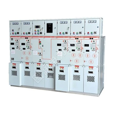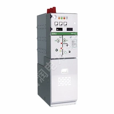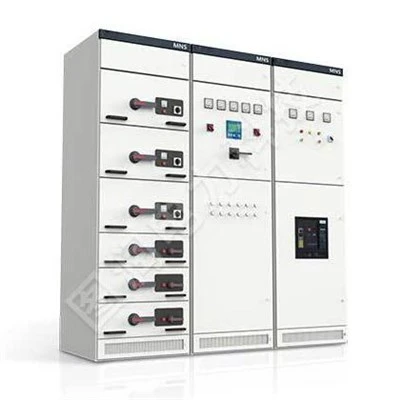

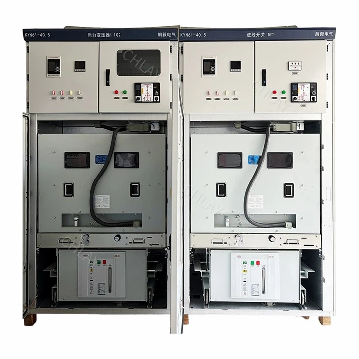
KYN61-40.5 Armored Removable AC Metal Switchgear
Overview
The KYN61-40.5 (Z) indoor high-voltage vacuum switchgear (hereinafter referred to as the switchgear) is a complete set of indoor power distribution equipment designed for three-phase AC systems with a frequency of 50 Hz and a rated voltage of 40.5 kV. It is used in power plants, substations, and industrial and mining enterprises to receive and distribute electrical energy, providing control, protection, and monitoring functions for circuits; it is also suitable for applications requiring frequent operation. This switchgear complies with standards such as GB/T 11022-2011, GB 3906-2006, and DL/T 404-2007. It features interlocking functions to prevent: closing the circuit breaker while the earthing switch is closed; accidental opening or closing of the circuit breaker; racking the circuit breaker truck in or out while under load; accidental entry into live compartments; and closing the earthing switch while the circuit is live.
Its main features include a metal-enclosed, armored, withdrawable structural design and the use of a new type of fully composite insulated vacuum circuit breaker. The cabinet utilizes an assembled structure, resulting in an aesthetically pleasing appearance, high precision in the fit between the truck and the cabinet, and excellent interchangeability. The movement of the truck within the cabinet is facilitated by a lead-screw and nut mechanism, making the operation convenient and effortless.
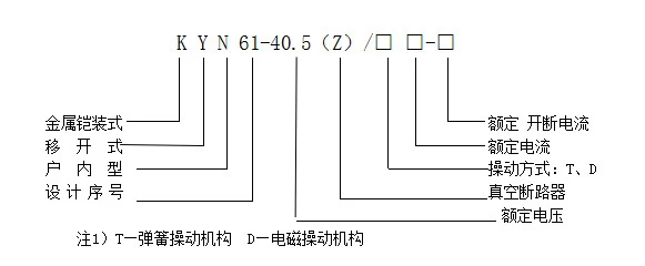
Composition and Meaning of Product Model Numbers
Service Conditions
3.1 Normal Service Conditions
a. Ambient air temperature: Upper limit +40°C, with the average value measured over a 24-hour period not exceeding 35°C;
Lower limit -25°C.
b. Altitude: Not exceeding 1000 m.
c. Relative humidity: Daily average not exceeding 95%, monthly average not exceeding 90%.
d. Seismic intensity: Not exceeding Grade 8.
e. Water vapor pressure: Daily average not exceeding 2.2 kPa, monthly average not exceeding 1.8 kPa.
f. Locations free from fire or explosion hazards, severe pollution, chemical corrosion, and intense vibration.
3.2 Special Service Conditions
For operation under conditions exceeding the normal environmental specifications stipulated in GB/T 11022-1999, the user and the manufacturer shall reach an agreement through consultation.
Overall Dimensions and Weight (see Figure 1)
Overall dimensions (Width × Depth × Height): 1400 (1200) × 2800 × 2600; weight: approx. 1800 kg.

Figure 1 Schematic diagram of the internal structure and external appearance of the KYN61-40.5 switchgear.
Technical Parameters
■ Technical Parameters of the Switchgear
|
Item |
Unit |
Parameter |
|
Rated voltage |
kV |
40.5 |
|
Rated current |
A |
1250, 1600, 2000 |
|
Rated frequency |
Hz |
50 |
|
Rated short-time withstand current (4s) |
kA |
25, 31.5 |
|
Rated peak withstand current* |
kA |
63, 80 |
|
Rated power-frequency withstand voltage |
kV |
95 (1 min) |
|
Rated lightning impulse withstand voltage |
kV |
185 |
|
Degree of protection |
|
Enclosure: IP3X; Between compartments: IP2X |
■ Main Technical Parameters of ZN85-40.5 Vacuum Circuit Breaker
|
Item |
Unit |
Parameter |
|
|
Rated voltage |
kV |
40.5 |
|
|
Rated frequency |
Hz |
50 |
|
|
Rated power-frequency withstand voltage |
kV |
95/1min |
|
|
Rated lightning impulse withstand voltage |
kV |
185 |
|
|
Rated current |
A |
1250, 1600, 2000 |
|
|
Rated short-time withstand current |
kA |
25, 31.5 |
|
|
Rated short-circuit breaking current |
kA |
25, 31.5 |
|
|
Rated peak withstand current |
kA |
63, 80 |
|
|
Rated short-circuit duration |
s |
4 |
|
|
Opening time |
ms |
≤60 |
|
|
Closing time |
ms |
≤100 |
|
|
Number of operations at rated short-circuit breaking current |
Operations |
20 |
|
|
Mechanical endurance |
Operations |
10000 |
|
|
Rated operating sequence |
|
Open-0.3s-Close/Open-180s-Close/Open |
|
|
Phase center distance |
mm |
300 |
|
|
Contact opening distance |
mm |
20±2 |
|
|
Overtravel |
mm |
5±1 |
|
|
Three-phase opening/closing non-simultaneity |
ms |
≤2 |
|
|
Contact closing contact pressure |
ms |
≤3 |
|
|
Closing contact pressure 3200±200 |
N |
25kA |
31.5kA |
|
Average opening speed (contact separation to 12mm) |
m/s |
1.8±0.2 |
|
|
Average closing speed (12mm to contact closure) |
m/s |
0.6±0.2 |
|
|
Opening time |
ms |
≤60 |
|
|
Closing time |
ms |
≤100 |
|
■ Technical Parameters of Closing and Opening Coils; Main Technical Parameters of the Spring Operating Mechanism for the ZN85-40.5 Vacuum Circuit Breaker
|
|
Closing coil |
Opening coil |
|
Rated operating voltage (V) |
DC 220V, DC 110V |
|
|
Coil power (W) |
AC 220V, AC 110V |
DC 220V, DC 110V |
|
Normal operating voltage range |
AC 220V, AC 110V |
■ Main Technical Parameters of FP40 Series SF6 Circuit Breakers
|
Maximum operating voltagekV |
Insulation level |
Breaking current |
Operating current A |
||||||||
|
Impulse withstand voltage kVP |
Power-frequency withstand voltage50Hz |
||||||||||
|
400 |
630 |
800 |
1250 |
1600 |
2000 |
2500 |
3150 |
||||
|
40.5 |
185 |
95 |
12.5 |
FP4012A |
FP4012B |
FP4012C |
FP4012D |
|
|
|
|
|
|
|
|
16 |
|
FP4016B |
FP4016C |
FP4016D |
FP4016E |
|
|
|
|
|
|
|
20 |
|
|
FP4020C |
FP4020D |
FP4020E |
FP4020F |
FP4020G |
FP4020H |
|
|
|
|
25 |
|
|
FP4025C |
FP4025D |
FP4025E |
FP4025F |
FP4025G |
FP4025H |
|
|
|
|
31.5 |
|
|
|
|
|
|
|
|
■ Main Technical Parameters of Schneider SF6 Sulfur Hexafluoride Circuit Breaker
|
Item |
Unit |
Parameter |
|
|
Rated voltage |
kV |
40.5 |
|
|
Rated insulation level |
Power-frequency withstand voltage |
kV |
95 |
|
Lightning impulse withstand voltage (peak value) |
185 |
||
|
Rated current |
A |
630 1250 2000 |
|
|
Rated short-circuit breaking current |
kA |
25,31.5 |
|
|
Rated short-circuit making current |
kA |
63,80 |
|
|
Rated short-time withstand current (3s) |
kA |
25,31.5 |
|
|
Rated peak withstand current |
kA |
63,80 |
|
|
Rated capacitor bank breaking current |
A |
440,875,1750 |
|
|
Number of short-circuit breaking operations |
次 |
20 |
|
|
Rated operating sequence |
|
分-0.3s-合分-180s-合分 |
|
|
Opening time |
ms |
45±4 |
|
|
Closing time |
ms |
68±4 |
|
|
Mechanical endurance |
次 |
10000 |
|
■ Technical Parameters of LZZBJ9-35 Current Transformer
|
Rated primary current(A) |
Accuracy Class Combination |
Rated output at the corresponding accuracy class(VA) |
Rated short-time withstand current (1s r.m.s. value) |
Rated peak withstand current (peak(kA)) |
||||
|
0.2 |
0.5 |
10P10 |
10P15 |
10P20 |
||||
|
30~100 |
0.2/10P10 |
15 |
30 |
50 |
30 |
20 |
150 1in |
375 1in |
|
150 |
0.2/10P15 |
15 |
30 |
50 |
30 |
20 |
31.5 |
80 |
|
200 |
0.2/10P20 |
15 |
30 |
50 |
30 |
20 |
44.5 |
80 |
|
300~500 |
0.5/10P10 |
15 |
30 |
50 |
30 |
20 |
54.5 |
80 |
|
600~800 |
0.5/10P15 |
30 |
50 |
50 |
40 |
30 |
63 |
80 |
■ LDBJ8-40.5Technical Parameters of Fully Encapsulated Epoxy Resin Cast Current Transformer (Contact Box Type)
Main Technical Parameters:
- Rated insulation level: 90/185 kV
- Rated secondary current: 5 A (or 2 A, 1 A)
- Partial discharge: ≤20 pC
- Accuracy class:0.2s,0.2,0.5,10P10,10P15,10P20
|
Rated primary current(A) |
Rated output at the corresponding accuracy class(VA) |
Rated short-time withstand current (1s r.m.s. value) |
Rated peak withstand current (peak (kA)) |
|||
|
0.2/10P10 |
0.5/10P10 |
0.2/0.5 |
10P10/10P10 |
|||
|
5~300 |
10/30 |
20/30 |
10/20 |
20/20 |
150 1in |
375 1in |
|
400~500 |
10/40 |
15/40 |
10/15 |
25/25 |
63 |
130 |
|
600~800 |
20/50 |
30/50 |
20/30 |
30/30 |
63 |
130 |
|
1000~1600 |
30/50 |
50/50 |
30/50 |
40/40 |
80 |
180 |
|
2000~3150 |
40/50 |
50/50 |
40/50 |
50/50 |
100 |
180 |
■ Technical Parameters of JN22-40.5/31.5 Earthing Switch
|
Project |
Unit |
Parameter |
|
|
Rated voltage |
kV |
40.5 |
|
|
Rated insulation level |
Power-frequency withstand voltage (1 min) |
kV |
95 |
|
Lightning impulse withstand voltage (peak value) |
185 |
||
|
Rated short-time withstand current (4s) |
kA |
31.5 |
|
|
Rated peak withstand current (peak) |
kA |
80 |
|
|
Rated short-circuit making current |
kA |
80 |
|
Structure and Operating Principle (See Figure 1)
The switchgear is designed in accordance with the GB3906-1991 standard for armored metal-enclosed switchgear. It consists of two main parts: the enclosure (cabinet body) and the withdrawable unit (i.e., the truck/carriage), as shown in Figure 1. The enclosure and the partitions between functional units are fabricated from aluminum-zinc coated steel sheets, processed and bent using CNC equipment, and assembled using rivet nuts and high-strength bolts; this method eliminates dimensional deviations caused by welding or human error, ensuring assembly precision. The enclosure is divided into four separate compartments, with an enclosure protection rating of IP3X.
It supports various functional configurations-such as overhead line or cable connections-that can be arranged and combined to form diverse power distribution schemes.
▅ Withdrawable Truck
The trucks are categorized by function into types such as circuit breaker trucks, voltage transformer trucks, metering trucks, and isolation trucks. All truck types share identical external dimensions, and trucks of the same function are interchangeable. Within the cabinet, the truck has "Test/Isolation" and "Service" positions; interlocking mechanisms ensure the truck cannot be moved arbitrarily while in either of these positions. A lead-screw and nut mechanism is used to move the trucks in and out, ensuring smooth and effortless operation.
When a truck enters the circuit breaker compartment, it must be securely locked in the "Test/Isolation" position. Only after it is fully locked and the cabinet door is closed can the small access door for the operating handle be opened; the handle is then inserted and turned clockwise to drive the propulsion mechanism and move the truck to the "Service" position. Once the truck reaches the "Service" position, the handle can no longer be turned, and a voice prompt indicates that the truck has arrived. A mechanical interlock ensures the truck can only be moved when the circuit breaker is in the open (OFF) position.
When the truck is securely locked inside the cabinet, the earthing switch cannot be operated; the earthing switch interlock must be released, or the truck withdrawn from the cabinet, before the earthing switch can be operated. If the earthing switch is in the closed (ON) position, the truck cannot be securely locked upon entering the "Test/Isolation" position, thereby preventing it from being moved to the "Service" position. 6.2 Compartments
The main electrical components of the switchgear are housed in independent compartments (see Figure 1): A. Relay and instrument compartment, B. Busbar compartment, C. Circuit breaker truck compartment, and D. Cable compartment. Adjacent compartments are separated by grounded metal partitions, forming a fully enclosed, metal-clad assembly with an inter-compartment protection rating of IP2X.
● Relay and Instrument Compartment (A)
This compartment accommodates protective relays, instruments, live-circuit indicators, and other secondary equipment as required. Access holes for auxiliary busbars are provided in the top panel to facilitate installation. The top cover plate can be flipped open during wiring to allow easy installation of the auxiliary busbars.
● Busbar Compartment (B)
The main busbars are arranged for interconnection between adjacent units and are supported by branch busbars and stationary contact housings. Both main and tie busbars consist of rectangular copper bars covered with heat-shrinkable tubing. All connection joints are enclosed in specially shaped heat-shrinkable sleeves (e.g., I-shaped, T-shaped, or L-shaped) to meet composite insulation requirements. Busbar bushings secure and isolate the busbars between adjacent cabinets; in the event of an internal arc fault, these bushings prevent the arc from burning through the barrier, effectively containing the fault within the compartment and preventing it from spreading to other cabinets.
● Circuit Breaker Compartment (C)
The circuit breaker compartment is located in the lower front section of the cabinet. A metal shutter mechanism, capable of opening and closing, is mounted on the rear partition, and rails are installed at the bottom to guide the movement of the circuit breaker truck. As the truck moves from the "test/isolated" position to the "service" position, the shutters covering the upper and lower stationary contact housings are mechanically linked to the truck via steel cables and open automatically; conversely, when the truck moves in the opposite direction, the shutters close automatically, fully covering the stationary contact housings once the truck retracts to a specific position, thereby ensuring effective isolation. The truck locking mechanism and the interlocking components connecting to the cabinet structure are located on the left and right sides of the front of the cabinet. 6.2.4 Cable Compartment D
The cable compartment accommodates current transformers, a grounding switch capable of making an 80kA short-circuit current, and power cables. Ample space facilitates the connection of multiple cables, and the cabinet bottom features removable non-magnetic metal cover plates to ensure ease of installation.
▅ Interlocking Devices to Prevent Misoperation
The switchgear is equipped with safe and reliable interlocking devices that fully meet the "Five-Prevention" requirements:
a. The truck can only be moved from the test/disconnected position to the service position when the grounding switch is in the open position; furthermore, the rear door cannot be opened, preventing accidental entry into a live compartment.
b. The grounding switch can only be closed when the truck is fully withdrawn from the cabinet, or when the truck is in the test/disconnected position and the grounding switch interlock is released; the grounding switch cannot be closed when the truck is in the service position. This prevents the grounding switch from being closed while the circuit is live and prevents the truck from being moved to the service position while the grounding switch is closed.
c. The circuit breaker can only be operated when the truck is in the test position or the service position; additionally, the truck cannot be moved after the circuit breaker is closed, preventing the circuit breaker from being racked in or out while under load.
d. Electrical interlocking can be installed between cabinet units.
▅ Pressure Relief Devices
Pressure relief devices are installed above the circuit breaker truck compartment, the busbar compartment, and the cable compartment. In the event of an internal arc fault in the circuit breaker or busbar compartment, the resulting rise in internal pressure causes the top-mounted metal pressure relief plate to open, releasing pressure and gases to ensure the safety of personnel and equipment.
▅ Live-Line Indication Device
Upon user request, the switchgear can be equipped with a live-line indication device to monitor the operation of the primary circuit. This device consists of a high-voltage sensor and an indicator, providing continuous monitoring of the high-voltage circuit's live status. 6.6 Anti-Condensation Device
To prevent hazards caused by condensation in climates characterized by high humidity and significant temperature fluctuations, heaters can be installed in the circuit breaker and cable compartments upon user request; these serve to prevent insulation degradation and condensation.
▅ Grounding Device
A dedicated 6×50 mm² copper grounding busbar is installed in the cable compartment. This busbar runs through adjacent cabinets and maintains good electrical contact with the cabinet structures. It is available for the direct grounding of components.
Hot Tags: withdrawable switchgear, China withdrawable switchgear manufacturers, suppliers, factory